CASIO
MT-750 |
|
midsize
ToneBank MIDI
keyboard with
simple synth |
|
|
|
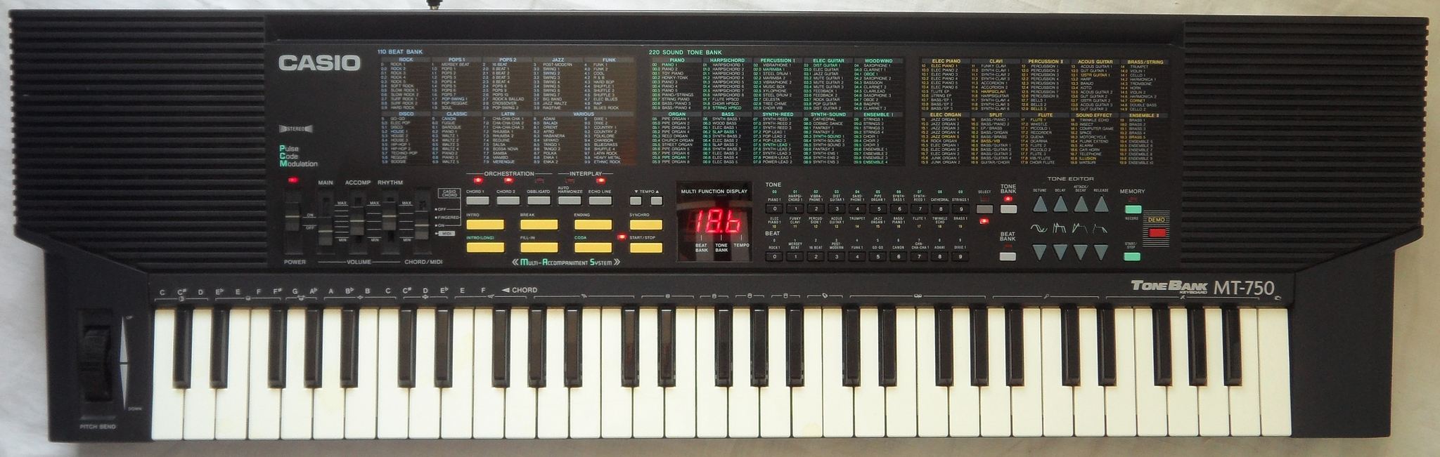
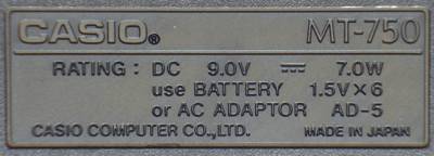
The Casio MT-750 of 1989 (service manual date) was the midsize
version of typical midi capable ToneBank home keyboards made after MT-540.
Despite similar hardware it focussed on having many instead of complex
sounds.
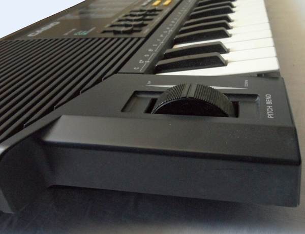
For a midsize keyboard 61 keys and pitchbend was very unusual, but Casio
made plenty of fullsize instruments based on this. Unfortunately all these
midi keyboards lack the complex algorithmic "PCM" softsynth sounds from
SA-series,
so most sounds are a bit boring. But the MT-750 wavetable sounds (often
mixed waveform samples with clever envelopes) still can contain reverb,
echo and stereo effects and have more character than long sample based
later CTK-series garbage from GM era. So it can do nice synth pads and
strings and has a couple of drumkits. Unfortunately everything is very
preset without sustain or vibrato buttons, but with the "tone edit" buttons
it has a kind of simple synthesizer that can change 4 parameters of the
preset sounds, but nothing can be saved or controlled by midi. The accompaniment
is more versatile than average, but can not play non-chords nor change
volume of its individual channels. Beside it has no velocity, the the tone
quality is still as good as modern beginners keyboard and better than many
noname tablehooters.
A fullsize version of MT-750 came out in 1990 (service manual date)
as Casio CT-670.
main features:
-
61 midsize keys
-
pitchbend wheel
-
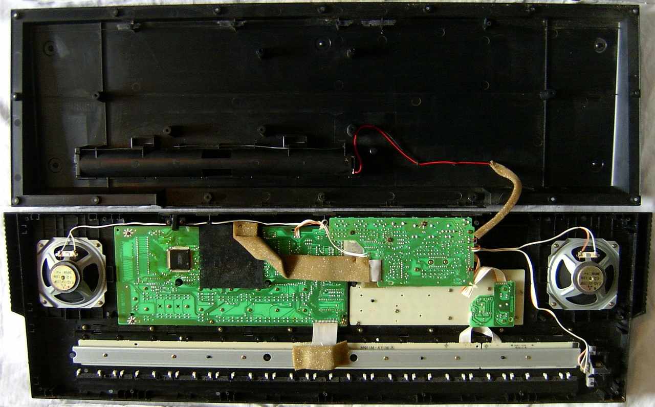
2 built-in 10cm speakers (stereo, good quality)
-
polyphony up to 12 notes (4 with chord or accompaniment, 2 with autoharmonize,
some sounds use 2 channels)
-
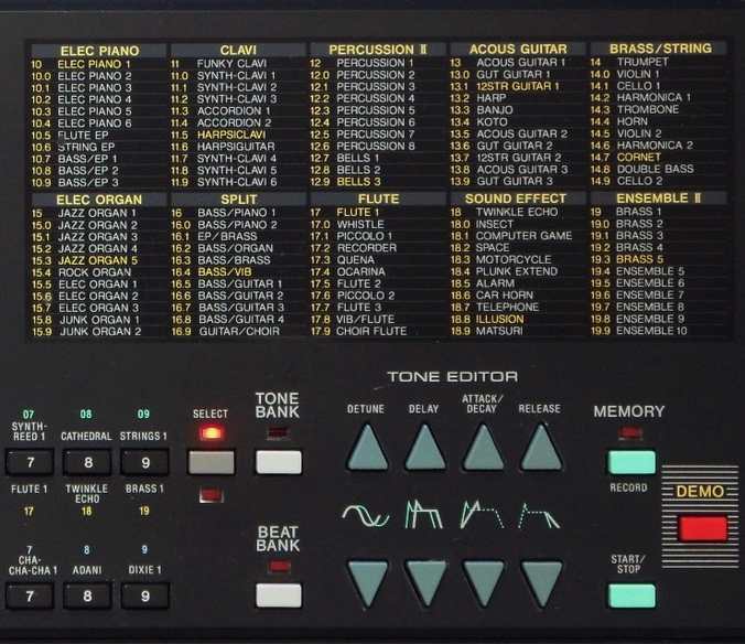
220 preset sounds: semi-OBS basic {piano 1, harpsichord 1, vibraphone 1,
dist guitar 1, saxophone 1, pipe organ 1, synth bass 1, synth reed 1, cathedral,
strings 1 | elec piano 1, funky clavi, percussion 1, acous guitar 1, trumpet,
jazz organ 1, bass/piano 1, flute 1, twinkle echo, brass 1} with each 11
variants
-
110 preset rhythms: OBS basic {rock 1, mersey beat, 16 beat, post modern,
funk 1, go-go, canon, cha-cha-cha 1, adani, dixie 1} with each 11 variants
-
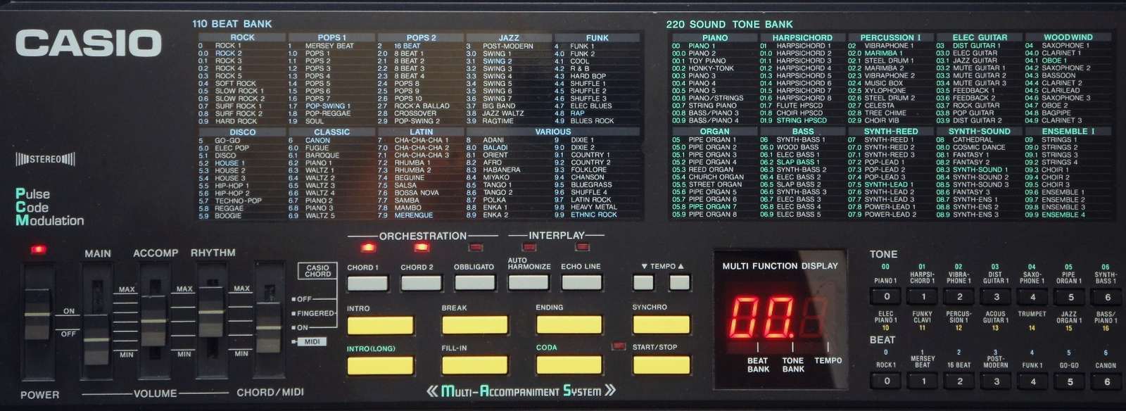
volume sliders {main, accomp. (5 steps), rhythm (5 steps)}
-
fingered & single finger chord
-
complex accompaniment:
-
"musical controller" buttons {intro, intro (long), break, fill-in, coda,
ending, synchro, start/stop}
-
"orchestration" buttons {chord 1 & 2, obligato}
-
"interplay" buttons [auto harmonize, echo line}
-
tempo +/- buttons
-
"tone editor" synth buttons {detune, delay, attack/decay, release} (each
+/-)
-
LED display (3 digits)
-
simple sequencer (record & playback of all sounds and changes, no edit,
ca. 1250 notes)
-
wavetable sound generator
-
multi- chip hardware:
-
CPU= "NEC D937GD 003, 9027B3012, Japan"
(SMD)
-
ROM= "Panasonic MN238000CUB, 05050, Japan" (42 pin DIL, 1MB)
-
SRAM= "OKI M5165AL-12, 073016, Japan" (28 pin DIL, , 8KB, PCB label "uPD4364C-12L.15L")
-
DAC= "Sanyo LC7880,
9C789" (20 pin DIL)
-
auto power-off
-
demo "The Way that you Love Me" by Paula Abdul
-
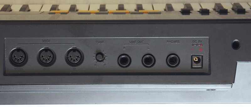
tuning knob
-
jacks for AC adapter, headphone, lineout, MIDI in+out+through
eastereggs:
sustain pedal addable.
modifications:
-
polarity protection diode added, power supply jack polarity changed to
standard.
notes:
For a midsize keyboard the MT-750 is rather bulky and takes almost as much
space as a compact 61 fullsizes keys instrument. But so it also has nice
internal speakers with enough bass. While the MT-750 itself is a bit rare,
plenty of fullsize variants can be found easily. The timbre quality is
more hifi and warmer than SA-series,
but the sounds are less complex. Fortunately it still had no audible split
zones, those distract in later sample based CTK-series tablehooters and
made them sound so cheapish. It rather seems to smoothly blend between
some waveforms, which is much more pleasant.
The preset sounds and rhythms are sorted in an strange way. They have
both their own row of cipher buttons. Type one digit to get a "basic" rhythm.
Then press "beat bank" button and enter a further digit for the listed
"bank" variants. The same principle is used with preset sounds, those have
an additional "select" button for 2 rows and a "tone bank" button. Apparently
Casio tried to make the user interface act like (semi-) OBS buttons by
placing on each cipher button what they proclaimed to be the most important
preset rhythms and sounds (including "select" button for a 2nd row). But
if you won't agree with their choice, this idiotic concept makes everything
just awkward, because the bank mode behaves like submenus, so to change
a sound you have to press the "tone bank" button again to exit the submenu,
press a cipher button (and sometimes "select") for a new main sound, again
"tone bank" to dive into its submenu and another cipher button to select
the item. Yuck! - Most newer keyboards (and even their own SA-series) simply
use multi-digit numbers.
Instead of a proper keysplit mode, there is only a preset sound category
"split" with 11 fixed combinations. Some synth effect sounds with same
name like in SA-series are totally different. Instead of wicked program
loop synthesis noises the most complex sounds here can only do siren envelopes,
echo, panning, loop samples and can contain split points with different
sounds on keyboard sections (like drumkit modes). This instrument tries
hard to keep a hifi appeal and contains nothing distorting or glitchy.
It sounds not bad, but does only things you would expect from a basic synth
with many standard envelopes and no VCF, and nothing that in any way surprises
or puzzles you how this effect could be done.
Like in many "modern" home keyboards, the user interface feels somewhat
intrusive. So the chord section stubbornly refuses to sound non-chords,
and its behaviour (a chord sounds until all chord section keys are released)
and sound can not be changed. The accompaniment styles have each a short
and long intro and ending (long is "coda"), but you can not make it dynamically
cancel an ending pattern by switching to break, intro or fill-in (a feature
I remember from Yamaha). There are mute buttons for 3 parts {chord 1, chord
2, obligato}. Depending on rhythm, "chord 2" can be e.g. the arpeggio.
But the mixing ratio of part volumes can not be changed. The MT-750 includes
some nicely unusual accompaniments like oriental or japanese styles. Many
are overorchestrated, but can be tamed by muting parts. "auto harmonize"
plays main voice as trio matching the chord. Most spectacular is "echo
line", which replies to your own melody notes delayed on a chord voice;
this is an rudimentary kind of realtime composing algorithm, that I only
knew from Technics K350.
They "tone editor" synth buttons "detune" (honkytonk piano effect) and
"delay" affect the subvoice of the right stereo channel. These panning
gimmicks resemble Casiotone
7000. The "attack/decay" up button makes later attack and slower
decay and down the opposite. "release" changes the attenuation. The values
can be neither displayed nor saved nor controlled by midi, and get reset
by selecting a preset sound.
The demo song is a funky pop track "The Way that you Love Me" by Paula
Abdul.
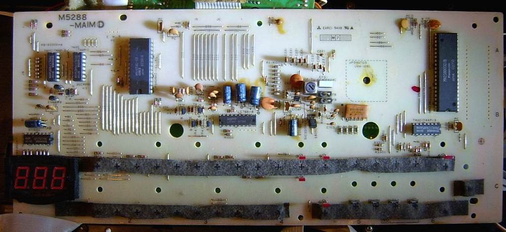
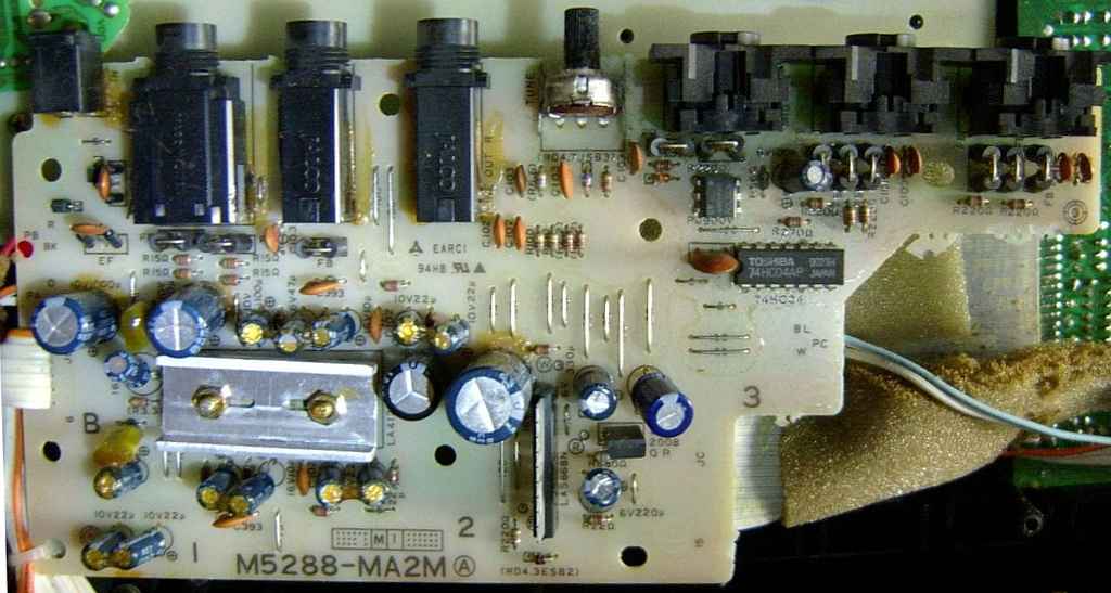
hardware details
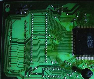
The Casio MT-750 is built around the CPU "NEC D937GD
003" with DAC "Sanyo LC7880",
external 1MB ROM "Panasonic MN238000CUB" and 8KB SRAM "OKI M5165AL-12".
The hardware is technically similar like MT-540
(see there) but the ROM samples are scrambled by swapped address and data
pins. It is unknown whether Casio did this as a crude copy protection or
to simplify PCB layout. My MT-750 of july 1991 has one 1MB 16-bit ROM "Panasonic
MN238000CUB" (and empty holes for a 2nd ROM with traces for the upper half
ending nowhere), but its service manual (november 1989, even in part list)
depicts in 8-bit mode 2x ROM "uPD23C4000A" with software numbers 65 and
66. Also the almost identical fullsize version
CT-670 has those
2x 8-bit ROMs (told by e-mail and seen in service manual).
The tone editor synth is described in patents US5044251 and US5177314.
keyboard matrix
This keyboard matrix is based on the Casio MT-750 and CT-670 service manual.
I haven't analyzed it by myself, so there may be still unknown eastereggs.
Particularly low-end keyboards of this hardware class (e.g. CT-655, CT-657)
have less features by omitted buttons, which perhaps was the main reason
for designing the awkward user interface. The CT-680 (CT-670 variant with
reverb) has no separate rhythm volume switch, so it likely has its accomp
volume slider connected through diodes to KO15 and KO16, which may be undone
to control both separately.
Like with MT-540, the hair thin CPU pins are not safe to mess with,
because they tend to short by debris. Thus measure at PCB solder joints
instead.
|
30 KI1
|
29 KI2
|
28 KI3
|
27 KI4
|
26 KI5
|
25 KI6
|
24 KI7
|
23 KI8
|
|
CPU pin
|
|
in 1
|
in 2
|
in 3
|
in 4
|
in 5
|
in 6
|
in 7
|
in 8
|
in / out
|
|
tempo
-
|
tempo
+
|
o
C1
|
o
C#1
|
o
D1
|
o
D#1
|
o
E1
|
o
F1
|
out 0
|
19 KO0
|
SY.
detune
+
|
SY.
detune
-
|
o
F#1
|
o
G1
|
o
G#1
|
o
A1
|
o
A#1
|
o
B1
|
out 1
|
20 KO1
|
SY.
delay
+
|
SY.
delay
-
|
o
C2
|
o
C#2
|
o
D2
|
o
D#2
|
o
E2
|
o
F2
|
out 2
|
21 KO2
|
SY.
attack/decay
+
|
SY.
attack/decay
-
|
o
F#2
|
o
G2
|
o
G#2
|
o
A2
|
o
A#2
|
o
B2
|
out 3
|
22 KO3
|
SY.
release
+
|
SY.
release
-
|
o
C3
|
o
C#3
|
o
D3
|
o
D#3
|
o
E3
|
o
F3
|
out 4
|
49 KO4
|
S.
start/stop
|
S.
record
|
o
F#3
|
o
G3
|
o
G#3
|
o
A3
|
o
A#3
|
o
B3
|
out 5
|
48 KO5
|
R.
synchro
|
R.
start/stop
|
o
C4
|
o
C#4
|
o
D4
|
o
D#4
|
o
E4
|
o
F4
|
out 6
|
47 KO6
|
C.
obligato
|
demo
|
o
F#4
|
o
G4
|
o
G#4
|
o
A4
|
o
A#4
|
o
B4
|
out 7
|
46 KO7
|
C.
chord 2
|
C.
chord 1
|
o
C5
|
o
C#5
|
o
D5
|
o
D#5
|
o
E5
|
o
F5
|
out 8
|
45 KO8
|
C.
echo line
|
C.
auto harmonize
|
o
F#5
|
o
G5
|
o
G#5
|
o
A5
|
o
A#5
|
o
B5
|
out 9
|
44 KO9
|
C.
fill-in
|
C.
break
|
o
C6
|
O.
select
|
O.
tone bank
|
R.
beat bank
|
C.
ending
|
C.
coda
|
out 10
|
43 KO10
|
R.
'5'
|
R.
'4'
|
R.
'3'
|
R.
'2'
|
R.
'1'
|
R.
'0'
|
C.
intro (long)
|
C.
intro
|
out 11
|
42 KO11
|
O.
'3'
|
O.
'2'
|
O.
'1'
|
O.
'0'
|
R.
'9'
|
R.
'8'
|
R.
'7'
|
R.
'6'
|
out 12
|
41 KO12
|
| |
|
O.
'9'
|
O.
'8'
|
O.
'7'
|
O.
'6'
|
O.
'5'
|
O.
'4'
|
out 13
|
40 KO13
|
C.
off
|
C.
fingered
|
C.
single finger
|
C.
midi
|
|
power
on
|
power
off
|
|
out 14
|
39 KO14
|
R.
volume 0
|
R.
volume 1
|
R.
volume 2
|
R.
volume 3
|
R.
volume 4
|
|
sustain pedal
|
|
out 15
|
38 KO15
|
C.
volume 0
|
C.
volume 1
|
C.
volume 2
|
C.
volume 3
|
C.
volume 4
|
|
|
|
out 16
|
37 KO16
|
The input lines are active-high, i.e. react on +Vs. Any functions can
be triggered by a non- locking switch in series to a diode from one "out"
to one "in" pin.
legend:
|
|
|
"o"
|
= keyboard key |
|
underlined
|
= function needs locking switch (i.e. stays active only so long the
switch is closed) |
|
R.
|
= preset rhythm |
|
O.
|
= preset sound ('orchestra') |
|
C.
|
= chord/accompaniment |
|
S.
|
= sequencer |
|
SY.
|
= synthesizer |
orange
background |
= easteregg (unconnected feature) |
grey
background |
= unconnected doublet |
The sustain pedal exists in CT-670, where it is wired through an inverter
and transistor. You may wire a switch here to hold notes.
The panel LEDs are latched from pins KO0..KO5 by 74HC174-2 during a
pulse on KO18 and by 74HC174-3 during a pulse on KO17. The LED display
is demuxed through HC4511AP from pins KO0..3 during a pulse on KO19 and
the segments are latched by 74HC174-1 from KO0..KO3 during a pulse on KO20.
pinout D937GD
The "NEC D938GD xxx" CPU (120 pin SMD, pins count counterclockwise, xxx
= software number of internal ROM) was used in many early Casio ToneBank
keyboards with midi. It has fully digital sound envelope processing and
mixing. All volume controls of individual sound channels (rhythm, accompaniment
etc.) are digital. Polyphony is 12 notes. The digital audio channels are
output as multiplexed serial data for left & right channel to an external
16 bit DAC (Sanyo LC7880). The CPU has 3 ADC inputs for reading analogue
signals (e.g. pitchbend). An external SRAM "NEC D4364C" is used for sequencer.
Sequencer RAM and LED lines are multiplexed with the keyboard matrix. The
CPU needs an external 16bit ROM (or 2x 8-bit) for wavetable samples and
data. Despite this it also has also internal ROM, which seems to contain
things like basic key matrix and user interface behaviour (those stay present
even with external ROM removed).
The MT-750 and CT-670 have software number "003".
This pinout is based on service manuals of Casio MT-750 and CT-670.
| pin |
name |
purpose |
| 1 |
VDD2 |
supply voltage +5V (when power on) |
| 2 |
/POFF |
power off signal out (not used) |
| 3 |
TEST1 |
test (wired to VDD1) |
| 4 |
TEST2 |
test (wired to VDD1) |
| 5 |
RESET1 |
reset |
| 6 |
MI |
power on trigger in |
| 7 |
TCLK |
(wired to VDD1) |
| 8 |
COSI |
crystal in | clock in (21.7248 MHz) |
| 9 |
COSO |
crystal out |
| 10 |
VDD1 |
supply voltage +5V (always on) |
| 11 |
MPG |
4 MHz clock test out (unbuffered) |
| 12 |
GND |
ground 0V |
| 13 |
MOSI |
midi & rhythm tempo crystal in | clock in (4MHz) |
| 14 |
MOSO |
midi & rhythm tempo crystal out |
| 15 |
INTF |
(not used) |
| 16 |
INT4 |
(wired to VDD1) |
| 17 |
MOUT |
midi-out |
| 18 |
MIN |
midi-in |
| 19 |
KO0 |
key & led matrix out |
| 20 |
KO1 |
key & led matrix out |
| 21 |
KO2 |
key & led matrix out |
| 22 |
KO3 |
key & led matrix out |
| 23 |
KI8 |
key matrix in |
| 24 |
KI7 |
key matrix in |
| 25 |
KI6 |
key matrix in |
| 26 |
KI5 |
key matrix in |
| 27 |
KI4 |
key matrix in |
| 28 |
KI3 |
key matrix in |
| 29 |
KI2 |
key matrix in |
| 30 |
KI1 |
key matrix in |
| 31 |
KO22 |
APO auto power-off /out |
| 32 |
KO21 |
(not used) |
| 33 |
KO20 |
led matrix latch out |
| 34 |
KO19 |
led matrix latch out |
| 35 |
KO18 |
led matrix latch out |
| 36 |
KO17 |
led matrix latch out |
| 37 |
KO16 |
key matrix out, ram address A12 |
| 38 |
KO15 |
key matrix out, ram address A11 |
| 39 |
KO14 |
key matrix out, ram address A10 |
| 40 |
KO13 |
key matrix out, ram address A9 |
| 41 |
KO12 |
key matrix out, ram address A8 |
| 42 |
KO11 |
key matrix out, ram address A7 |
| 43 |
KO10 |
key matrix out, ram address A6 |
| 44 |
KO9 |
key matrix out, ram address A5 |
| 45 |
KO8 |
key matrix out, ram address A4 |
| 46 |
KO7 |
key matrix out, ram address A3 |
| 47 |
KO6 |
key matrix out, ram address A2 |
| 48 |
KO5 |
key & led matrix out, ram address A1 |
| 49 |
KO4 |
key & led matrix out, ram address A0 |
| 50 |
/WE1 |
ram write enable |
| 51 |
/OE1 |
ram output enable |
| 52 |
/CE1 |
ram chip enable |
| 53 |
D0 |
ram data bus |
| 54 |
D1 |
ram data bus |
| 55 |
D2 |
ram data bus |
| 56 |
D3 |
ram data bus |
| 57 |
D4 |
ram data bus |
| 58 |
D5 |
ram data bus |
| 59 |
D6 |
ram data bus |
| 60 |
D7 |
ram data bus |
|
|
| pin |
name |
purpose |
| 61 |
IO0 |
rom1 data D0 in |
| 62 |
IO1 |
rom1 data D1 in |
| 63 |
IO2 |
rom1 data D2 in |
| 64 |
IO3 |
rom1 data D3 in |
| 65 |
IO4 |
rom1 data D4 in |
| 66 |
IO5 |
rom1 data D5 in |
| 67 |
IO6 |
rom1 data D6 in |
| 68 |
IO7 |
rom1 data D7 in |
| 69 |
IO8 |
rom2 data D4 in |
| 70 |
IO9 |
rom2 data D3 in |
| 71 |
IO10 |
rom2 data D5 in |
| 72 |
IO11 |
rom2 data D2 in |
| 73 |
IO12 |
rom2 data D6 in |
| 74 |
IO13 |
rom2 data D1 in |
| 75 |
IO14 |
rom2 data D7 in |
| 76 |
IO15 |
rom2 data D0 in |
| 77 |
BSEL |
(wired to GND) |
| 78 |
AR0 |
rom address A16 out |
| 79 |
AR1 |
rom address A0 out |
| 80 |
AR2 |
rom address A15 out |
| 81 |
AR3 |
rom address A1 out |
| 82 |
AR4 |
rom address A14 out |
| 83 |
AR5 |
rom address A2 out |
| 84 |
AR6 |
rom address A13 out |
| 85 |
AR7 |
rom address A3 out |
| 86 |
AR8 |
rom address A12 out |
| 87 |
AR9 |
rom address A4 out |
| 88 |
AR10 |
rom address A11 out |
| 89 |
AR11 |
rom address A5 out |
| 90 |
AR12 |
rom address A10 out |
| 91 |
AR13 |
rom address A6 out |
| 92 |
AR14 |
rom address A9 out |
| 93 |
AR15 |
rom address A7 out |
| 94 |
AR16 |
rom address A8 out |
| 95 |
AR17 |
rom address A17 out |
| 96 |
AR18 |
rom data D15 in |
| 97 |
AR19 |
rom chip enable /CE |
| 98 |
AR20 |
(not used) |
| 99 |
AR21 |
(not used) |
| 100 |
/CE |
rom data out enable |
| 101 |
/OE |
(not used) |
| 102 |
/WE |
(not used) |
| 103 |
/CEP |
(not used) |
| 104 |
RFSH |
(not used) |
| 105 |
MCLK |
main clock test out (2.7156MHz = 1/8 of 2.17248MHz) |
| 106 |
SWD4 |
(not used) |
| 107 |
BCLK |
DAC bit clock out |
| 108 |
SWD3 |
(not used) |
| 109 |
SWD1 (DATA) |
serial digital audio data out (16 bit multiplexed left
& right channel) |
| 110 |
SWD2 |
(not used) |
| 111 |
WCLK1 |
DAC word clock out |
| 112 |
LRCK |
DAC left /right channel separation signal |
| 113 |
STEST |
test (wired to VDD1) |
| 114 |
VRT |
ADC high level reference voltage (connect to DVDD +5V) |
| 115 |
ADVDD |
ADC supply voltage +5V |
| 116 |
Vin0 |
ADC pitchbend in |
| 117 |
Vin1 |
ADC analogue in (wired to 116) |
| 118 |
Vin2 |
ADC analogue in (wired to 116) |
| 119 |
ADGND |
ADC ground 0V |
| 120 |
VRB |
ADC low level reference voltage (wired to ground 0V) |
|
Unlike MT-540, the rom pins are shuffled in a strange order. The data
D# pins of rom2 (from MT-750 and CT-670 schematics) likely correspond to
the upper bits of the single 16-bit ROM version used in later MT-750 models.
The ROM contents is scrambled corresponding to the pin wiring, so the CPU
likely sees its address space unscrambled.
This CPU is a close relative (possibly software variant) of the D938GD
used in Casio MT-540. |
A fullsize version of MT-750 came out as Casio CT-670. This keyboard
was featured in "Casio Keyboard Lesson" VHS tapes with Richard Clayderman,
where he e.g. played the classical piano piece "Ballade Pour Adeline".
This keyboard was also released as Hohner PSK-75. A version with
"digital reverb" instead of rhythm volume slider was Casio CT-680
(aka Hohner PSK-75R). A 49 keys variant (no pitchbend) was Casio
CT-470 (aka Hohner PSK40 / PSK45). A variant with only
110 sounds was CT-655 / CT-656 (61 keys, no pitchbend, no
coda, only 56 rhythms by fewer buttons, different sound order = changed
rom? (demo is the same) | aka Hohner PSK60) and its even more crippled
variant
CT-657 (no midi, no detune, no break, no line echo, different
demo | aka Hohner PSK65).
attention: When a Casio keyboard has a "210 Sound Tone
Bank" or "465 Sound Tone Bank" label, then it generally seems to
have only 20 or 30 preset sounds (of those only any 2 can be layered to
form that many dual voice combinations) and thus has genuinely fewer
individual preset sounds than the later Casio "100 ToneBank" instruments
(of those e.g. my
CT-840 still can
layer any 2 sounds and thus can form even many more combinations).
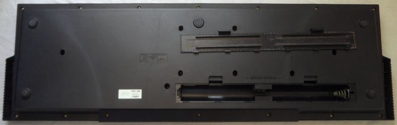
| removal
of these screws voids warranty... |
|
|
 |

|
|
| |
back
|
|