|
|
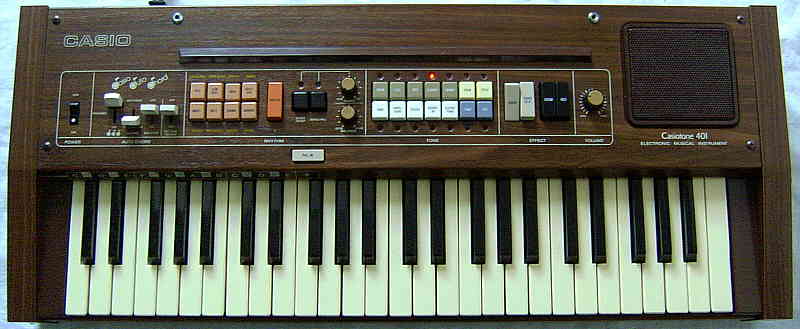
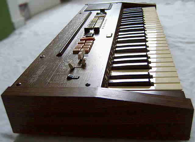
the first Casio keyboard with automatic accompaniment & rhythm |
|
This instrument from 1981 was Casio's first keyboard with accompaniment and (as far I remember well) also the world first keyboard with automatic single finger accompaniment.
 |
 |
 |
 |
 |
 |
 |
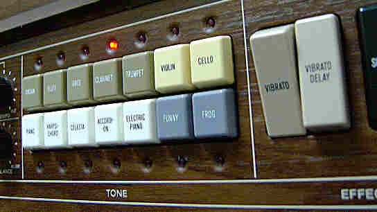
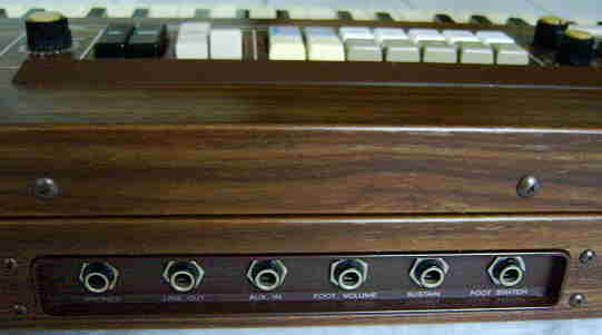
sound select button for 23 preset sounds with optional tone memory switch addable. likely different vibratos and spread tone scale switch addable. 1 octave lower chord channel output.
Like Casio CT-410V, the main voice sounds of the Casiotone 401 consist of 2 mixed stair waveform suboscillators with different pulse patterns and different digital volume envelopes, those are (depending on the preset) muffled by different filter capacitors. Thus both instruments have the same kind of sounds, although unlike the rather dull CT-410V, many sounds of the 401 have a reasonably bright and partly incredible dry timbre, and when a key is trilled with sustain, each new note here occupies a new sound channel, which produces a great phasing sound and volume increase effect although this eats up polyphony. In the bass range many sounds turn into a more or less buzzy, sonorous purring drone, which is a characteristic style element of squarewave based instruments. These basses can resemble some of the famous POKEY sound effects on Atari XL homecomputers and are very different from the gradually duller and duller growing sine wave bass behaviour of average Yamaha FM keyboard sounds. (For further technical details about this hardware family also see here.)
By the use of simple low pass filters, many sounds play high notes too quiet. The "organ" is a slightly dull metal pipe organ timbre, which seems to be a muffled variant of the that classic multipulse sound. The bass range reminds to a wooden accordion. The "flute" is dull and resembles a sine wave tone. As expected, "oboe" is harsher; the bass range resembles a saxophone. The "clarinet" turns thinner during its attack phase. The "trumpet" sounds quite thin and barely recognizable (like with many squarewave based instruments). The "violin" sounds ok (especially with vibrato), while the "cello" is dull and could be also a dull tuba or the like. The "piano" has a too dull bass range; the "electric piano" is the same in slightly brighter. The "harpsichord" sounds ok. The "celesta" is a musicbox sound that sounds unrealistic by a too slow attack phase; the timbre resembles a flute. The "accordion" has a fluttering attack phase (quickly quieter and louder again, more like a violin) and sounds too dull and plastic- like. The "funny" preset is a sort of rough digital slap bass (creaky picked e-bass) which sounds like "ennng!" (possibly it was initially intended to be called "funky", but sounded to artificial for this?). An even harsher variant of this is called "frog" (although it doesn't sound at all like one), which makes a wonderful rough and incredible dry bass noise. When sustain is switched off, all sounds stop almost immediately after releasing the key, and the sound presets itself also contain neither vibrato nor tremolo. The sustain duration depends on the preset sound. The vibrato is quite fast (6Hz) and its intensity depends on the preset sound. When "vibrato delay" is additionally pressed, the vibrato waits 1s before it starts (vibratos affect also sustain); with vibrato off this button does nothing. Very unusual is the "hold" switch, which makes the melody section of the keyboard behave like the manual fingered chord mode on most newer keyboards; the notes of any pressed key or key combination (e.g. chord) are held after key release, and after all keys are released, any newly pressed keys stops the old held notes and instead plays and holds the new ones. Apparently the algorithm of the manual fingered chord with chord memory was re-used for this. Despite there are nicely big semi- OBS preset sound buttons, they are no good realtime sound control since they mute held notes while pressed and cause a delay of about 0.3s after button release before held or new notes will sound again.
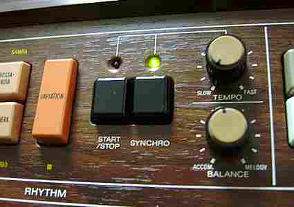
The percussion are typical soft analogue home organ drums; cymbals and snare are likely made from transistor noise. The patterns also include beside the usual stuff also a few nice latin rhythms and the "fill-in" button inserts a fill-in pattern (including accompaniment), which depends on the selected rhythm. Unusual is that during rhythm not only the "start/ stop" LED lights up during the first step of a bar, but both the red "start/ stop" and the (at that time expensive?) green "synchro" LED dimly flash during every step. Despite the locking button switches, the semi- OBS preset rhythm buttons switch a playing rhythm only at the end of the bar, which limits their use for realtime play tricks.
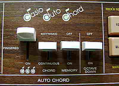
Unlike later Casio instruments, the accompaniment here was not yet called
"Casio Chord", but "Casio Auto Chord" (abbreviated "CAC"),
and it also did not feature yet an arpeggio. But the accompaniment of this
historical instrument already accepts any disharmonic note combinations
and not just those few ones that establishment has defined to be "chords".
Apparently there was already more software behind than with the archaic
Antonelli
Star 2379, because the bass pattern here only plays its note sequence
when it recognizes chord- like key combinations, while it plays only one
note during wild clusters or a single key press. Unusual with the 401is
the "chord" switch; when set to "rhythmic", you get the usual automatic
bass and chord accompaniment, but when set to "continuous" only the bass
plays automatic the note of the lowest pressed chord section key, while
all keys of the chord section otherwise are in manual organ chord note
like with rhythm off. The accompaniment patterns are made from a monophonic
bass line (some with walking bass) and simple staccatos of the current
chord (or note combination). The chord voice is a plain squarewave organ
tone, while the bass is a dull and warm organ bass tone with sustain that
reminds to a dull Roland TB-303 bass and may be made from a triangular
wave. With rhythm off there is a manual chord mode (12 note polyphonic!)
with bass on the lowest played key. Unfortunately also here the notes always
stay within 1 octave, thus it is no real key split. Regard that with this
ancient Casio the chord section will not play any sound when the "chord"
switch is set to "rhythm" while rhythm is off. With the "memory" switch
the current chord is held after key release (with or without rhythm). Moving
the "chord" lever switch slowly during rhythm varies the chord volume,
which can be also used musically.
circuit bending detailsThe Casiotone 401 uses the main voice CPU NEC D773G, which is an early member of the D77xG family. The accompaniment CPU "NEC D8049C 084" is an MCS-48 microcontroller with 2KB ROM (I dumped it) that controls through I/O IC NEC D8243C the chord section tone generator "Texas Instruments TMS3615NS", which is socketed by unknown reason. Because Casiotone 301 (same hardware without accompaniment) came first, it may be that a shortage of that IC prevented finishing the 401, so the TMS3615NS could be installed last when the rest was already completed.
I initially had no service manual of the 401, but got a photocopy of Casiotone 403, which was of great help to understand the general hardware architecture, because it has the same accompaniment hardware combined with the main voice section of Casio MT-60 (first 403 models had CPU version D776G with external bugfix circuitry). They are a good didactic example how Casio in early instruments made several different CPUs cooperate and combine their keyboard matrices rather than the centralized master-slave approach found in later hardware, and how despite almost self-contained CPUs often minor functions like clock rate conversion or preventing wrong key press order during preset sound selection used a crazy amount of "glue logics" ICs cluttering up the mainboard. Later I found the service manual PDF of Casiotone 401. The preset sounds are routed through switchable lowpass filters. The
cutoff frequencies are set by main voice CPU pins 42..47 (IO-31, IO-4,
IO-5, IO-6, IO-7, IO-8). In plain mode all filters are disabled.
SW1..SW7 are analogue switches in the filter schematics. The actual control line bits on main voice CPU out pins apparently differ; they seem to be mainly designed to identify each preset sound number. There are additional intermediate bits F1..F5 in a table below the handdrawn looking schematics (which unfortunately is cropped and fuzzy in the service manual PDF), those don't seem identical with SW1..SW7. The vibrato LFO modulates the 566 kHz clock speed of the main voice CPU D773G with a 6Hz triangular wave. This is bizarre because the main voice CPU already contains digital vibrato, which is not used. Delayed vibrato is implemented by an analogue circuit that gets resetted when there is no sound coming out of the DAC. Perhaps this was the only reason form this complicated solution, or digital vibrato was still missing in a prototype of the D77xG. The earlier release of Casiotone 301 without the (in 401 still socketed) chord IC may hint that Casio finished the 401 last-minute when functional chip features were still uncertain. Someone e-mailed me that in his Casiotone 701 the rare DAC IC "AM6012PC" died and that he successfully replaced 2 of them with the modern type "Analog Devices DAC312". It is unknown if these generally suffer of ageing, but another e-mail confirmed that they tend to die. The 401 has the same part connected with its main voice CPU, while the direct successor Casiotone 403 already had the DAC hybrid "EXK-SIOL0025C" (12 pin SIL) - possibly to improve reliability. The microcontroller based bass accompaniment with tone generator is described in US patent 4561338. There it uses for each 2-bar bass pattern 16 ROM addresses (4 bit) with 5 bit bass note data (31=silence) and 5 bit percussion data (1 bit per sound). When during 2nd bar any chord key is pressed or held, the 4th address bit of the bass note counter resets and so repeats the 1st bar. The accompaniment CPU outputs a monophonic squarewave tone and trigger pulse for the analogue bass envelope circuit, and trigger outs for analogue percussion. In the actual instrument it also controls the chord tone generator TMS3615NS through an I/O IC. Danger!: The IC TMS3615NS employs a +15V high supply voltage, which may destroy other ICs when accidentally shorted. Thus stay away from pin 4 and do not blindly poke around in the circuitry; also some logic ICs use this voltage. keyboard matrixDespite the keyboard matrix layout of the main voice CPU D773G is generic D77xG (i.e. preset sounds selected through keyboard keys), the sound select button was omitted and instead simulated by 14 LED-lit OBS preset sound buttons connected through logic gates, those feed the corresponding KI# lines during KO# with correct timing. This costly way was likely chosen to give it a more traditional home organ appeal to customers those felt scared off by the Casiotone 201 user interface upon a time that was not ready for sound bank instruments.
Unfortunately this wastes 9 of the 23 preset sounds buried in its CPU. I haven't analyzed the matrix by myself, but found info in Robin Whittle's great essay "Modifying the Casiotone Instruments" and finally the Casiotone 401 service manual. See Casio M-10 key matrix for the preset sound names of the remaining key. Apparently a hi pulse on pin 34 I-2 informs the main voice CPU when a preset sound button is pressed. In fingered or single finger chord mode the CPU inputs KC1..KC3 get disconnected by gate logics to prevent sounding the main voice by chord section keys. Matrix eastereggs are selected by each a locking switch in series to a diode at the following CPU pins:
CPU pin 16->30
CPU pin 17->30
CPU pin 16->29
CPU pin 17->29
CPU pin 16->28
CPU pin 17->28
CPU pin 16->17
CPU pin 17->27
CPU pin 16->26
CPU pin 16->25
CPU pin 16->31
CPU pin 18->29, 18->30
control panel matrixThis incomplete control panel matrix is based on the Casiotone 401 (initially also 403) service manual. While the output (KC) pins come from the main voice CPU, the input pins (SW) here are sensed only by the accompaniment CPU D8049C (which syncs itself to them through pin 39 waiting on the KC-1 pulse). Robin Whittle claimed in his essay, that the preset sound buttons of the 401 simulate to the main voice CPU the classic 'set' switch + keyboard key selection method (like with Casiotone 201) using logic ICs. I expect that also here the D8049C is involved; when removed, the buttons don't respond and the instrument stays mute.Panel LEDs are controlled through logic gates from main voice CPU pins
42..47, those also switch the fixed filters.
pinout D8049C-084The "NEC D8049C 084" (40 pin DIL) was the accompaniment CPU of the first polyphonic Casio keyboards with rhythm. It supports a keyboard matrix for chord section and control panel, and has separate outputs for 7 analogue percussion triggers, bass envelope trigger (for external analogue decay circuit) and 5 data pins those can be demultiplexed in an I/O port IC "NEC D8243C" to output a monophonic squarewave bass tone and control the chord tone generator "Texas Instruments TMS3615NS". Unlike later accompaniment CPUs it does not control a passive main voice sound IC, but reads 4 of the main CPU keyboard matrix outputs to sense chord section keys. To prevent these keys from sounding also the main voice, there need to be external AND gates in the lines to the main CPUs keyboard matrix inputs to disable them during chord play. The principle how this accompaniment CPU taps into a given keyboard matrix by listening to its output lines and intercepting inputsis exactly the same like what midi retrofit kits for non-midi keyboards do. Technically the "D8049C xxx" is a generic microcontroller of the well
documented Intel MCS-48 family, so everything it does is entirely controlled
by software of its internal 2KB ROM (I dumped it). So it makes no sense
to write down a combined pinout for all software variants of D8049C because
they differ too much. This pinout describes software number "084", based
on the Casiotone 403 service manual and Intel MCS-48 datasheets.
The tempo clock input to pin 6 is externally produced by a PUT (Programmable Unijunction Transistor) oscillator, which frequency depends on the tempo potentiometer. Rhythm can start only at the falling edge of it, therefore oscillation is forced into the next lo phase by a pulse from D8243C pin 15 to start rhythm immediately by a start button or chord key press (synchro start). The clock frequency for TMS3615 is divided from pin 1 output through a complicated gate and flipflop circuit (TC4001, 2x TC4013, TC4510BP). The I/O expander NEC D8243C converts
the chord data into this:
Pin 16 outputs the bass tone (monophonic squarewave) that is externally mixed with an analogue envelope controlled by D8049C pin 27; the tone is held so long it stays hi and then decays with capacitor envelope. The TMS3615NS produces 12 tones (full polyphonic notes of 1 octave with sustain) corresponding to the levels on the 12 chord bit outputs. pinout TMS3615The OMTS "Texas Instruments TMS3615NS" (28 pin SDIL, official name "Octave Multiple Tone Synthesizer") is used as a chord generator in the first polyphonic Casio keyboards with accompaniment. The IC derives from its clock rate the 12 tones of an octave (and a 13th tone) and outputs each of them so long the corresponding note input pin is hi(?). When the note stops, it falls silent with a decay envelope (sustain) that can be adjusted through an analogue control voltage input. This ancient PMOS IC was meant as an octave generator in full polyphonic 1970th home organs with very little digital control; a sign of its age is the unusually high +15V supply voltage (minimum +12V), which prevented easy battery operation and so made Casio soon abandon it. It can output 2 adjacent footages and sustain of the output is inplemented by external 1uF capacitor at each input, i.e. they are indeed VCA control voltages rather than digital. Pin 3 changes the pullup impedance of the key inputs and thus sustain length. The reset input is only used to synchronize the internal oscillators to control the phase in relation to other tone generators in the system. The clock out at half frequency was intended to daisychain these ICs in keyboards with multiple octaves. Interesting is that the TMS3615NS outputs 2 footages (e.g. for drawbar organs), thus an additional 1 octave lower version of the accompaniment (not used by Casio) exists on pin 16'OUT as an easteregg.The inner working of this IC is thoroughly described in patent US4358982 (priority date 1979 | thanks Traktor for info). The signal processing behind the frequency dividers is fully analogue, including a large bank of VCA multiplying the key voltage (and volume envelope) with each drawbar partial tone. For these, the patent detailedly explains voltage stabilization and a special automatic DC offset voltage compensation circuit based on clocked (class D PWM?) chopper amplifiers to prevent key click and distortion. This pinout is based on the Casiotone 403 service manual and TMS3615NS datasheet; in 403 schematics the IC is named "TMS 3615-25NS, RI-103" and also a 403 hardware photo shows "-25NS", so it may be a variant (clock speed like with RAM?). The variant RI107 outputs squarewave with 50% duty cycle, while RI103 has 25% at 8'OUT. warning: A bizarre bug in the TMS3615NS datasheet of novermber 1981 garbled its pinout page, so all its pin numbers up to 15 are 1 too high and the rest 1 too low (verified by Casiotone 401 PCB photo). Apparently they wrote it down wrongly from a chip package drawing (absent in datasheet) because GND is indeed pin 13, and 14 and 15 unused, so I shifted them to to fill in the unused pins here. Likely TI initially planned to produce this chip in a shorter package, but 24 pin SDIP was not available. On Vintage Chip I saw indeed a 24 pin DIL version for sale. A
hand drawn pinout on Flickr by synx508 indicates that in
Roland
HP-60 the SDIL version of TMS3615NS has the same pinout like mine,
suggesting that the other pinout was possibly used by an 28 pin DIL version.
In Casiotone 403 schematics the pin 3 SUS BIAS is between 2 resistors forming a voltage divider 33k to +VCC and 22k to GND. Pin 26 STB OUT goes to the "+" input of an op-amp and 100k pulldown to -15V. Pin 25 STB IN goes to a 3.3uF electrolytic cap against +15V and through a 220 Ohm resistor to the output of that op-amp. (Its "-" input is on GND.) According to datasheet this does automatic gain control to compensate temperature drift of the analogue circuit. If absent, STB IN should be wired to +VCC and STB OUT open. The datasheet suggests that against ESD damage(?) the pins SUS BIAS and STB IN should be connected through each a 0.5 megohm resistor to +VCC on the same PCB. |
A Casiotone 401 variant without accompaniment section was released
earlier (1980) as Casiotone 301 (seen on eBay - likely rarer
than the 401). This CT-301 had an identical case beside that
it lacks the 4 white switches, the letter row above leftmost keys, the
fill-in button and has only 4 jacks. Also the control panel sections are
in different order (power switch, 16 preset sound buttons, vibrato switches,
8 rhythm buttons, rhythm start/ stop & synchro switches, 3 knobs) and
employ the 2 black toggle switches here for rhythm start/ stop and synchro
instead of the missing sustain and hold functions. Also the orange rhythm
select switch apparently does something else, thus there are only 8 OBS
rhythms. The same main voice CPU was also used in the simple Casio
M-10. The accompaniment hardware of the 401 was later used in Casiotone
403 (seen in service manual) with main voice like Casio
MT-60.
| removal of these screws voids warranty... | ||
 |
||
|
|