hardware details
Danger!: Tube electronics works with
highvoltage that can cause deadly electric shocks or fire. Thus do not
repair or modify these unless you know what you are doing.
The tone generator modules contain dozens of of more or less rotten
"explosive candy" paper capacitors those reliability is very questionable.
As a safety measure I already replaced the ones in the power amplifier,
because the previous owner said that the amp crackled and smoked a bit
when he plugged in the HV connector of the organ during operation, and
because the EL12 power tubes are expensive to replace and a short in the
wooden cabinet could cause a fire. But to replace all of them in the organ
would be a tremendous lot of work. Unfortunately I not even have schematics
to determine the proper cap values for a replacement; the writing on the
cracked and dirty capacitors is partly badly readable. But I bought already
new capacitors and will repair this thing when I find time in future. This
strange thing is like a piece of ENIAC, and feels like repairing the tube
operated time machine in the movie "The Time Travelers" from 1964.
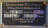
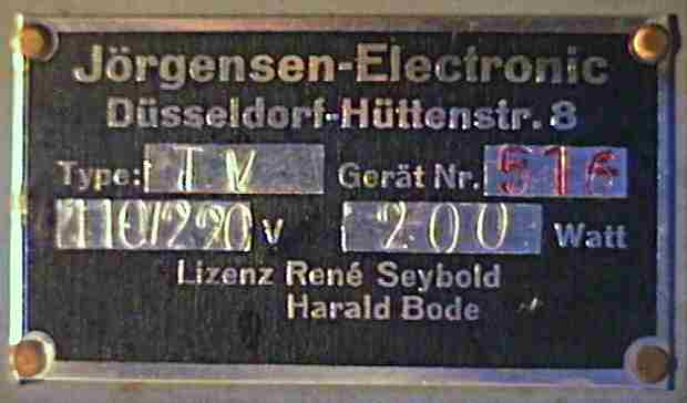
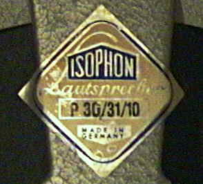
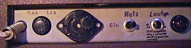
The amp's serial number plate. |
 Now
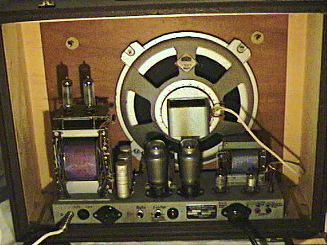
take a look what's inside... Now
take a look what's inside... |
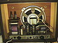 |
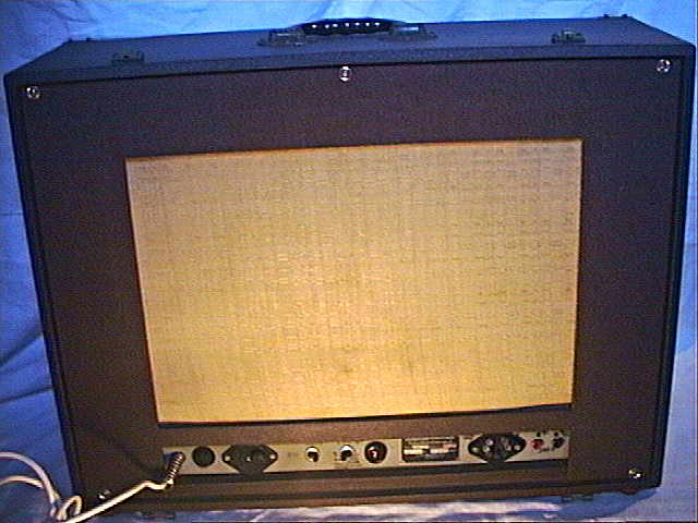
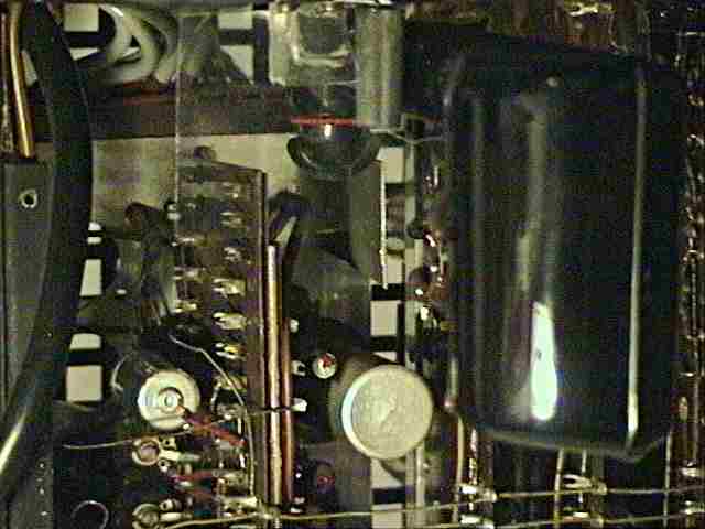
Here you see the large loudspeaker and the 2 big EL12 power tubes on
the chassis. |
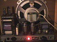 |
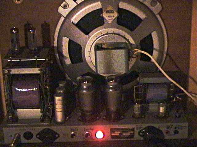
When on, you can see the tubes glow and the bright red shine of the
pilot lamp. |
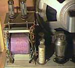 |
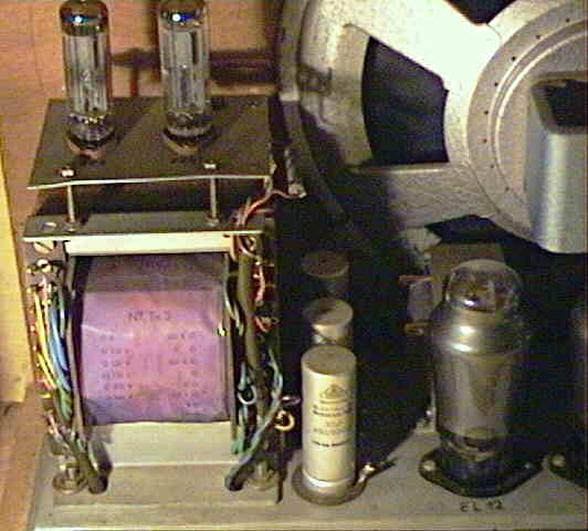
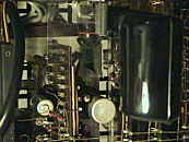
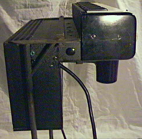
Although this mains transformer block may look small and harmless,
I estimate that its solid, heavy iron core incorporates at least 65% of
the weight of the entire amplifier.
Above it you see the 2 EZ81 rectifier tubes; in one of the EZ81 and
one EL12 tube there is weak blue ionization visible, possible a remain
from a previously broken grid capacitor. |
The instrument can play loud enough to annoy neighbours tonight, but I
don't think that it is louder than the amp of average 1x EL84 tube radios,
despite the 2x EL12 tubes look like something as big as KT88 and by their
appearance I would expect rather 30W power than just 5W. It may be that
the ionization in one tube eats up the power, or that just the huge loudspeaker
has lost most of its magnetism (which is rumoured to happen with that old
speakers), or that a small defect in the organ makes it quieter. (Its internal
preset volume trimmer is all way cranked up.)
The organ connector has this pinout: (counting left to right anticlockwise)
-
"-" 37.8V AC
-
"-" 6.3V AC
-
+300V DC
-
audio in
-
GND
-
"+" 6.3V AC
-
"+" 37.8V AC
|
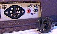 The
organ tube heaters are wired in series and supplied by the 37.8V AC output
(likely to reduce the needed current on the supply cable); the 6.3V output
is not used. The
organ tube heaters are wired in series and supplied by the 37.8V AC output
(likely to reduce the needed current on the supply cable); the 6.3V output
is not used. |
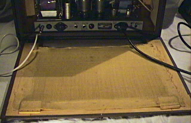
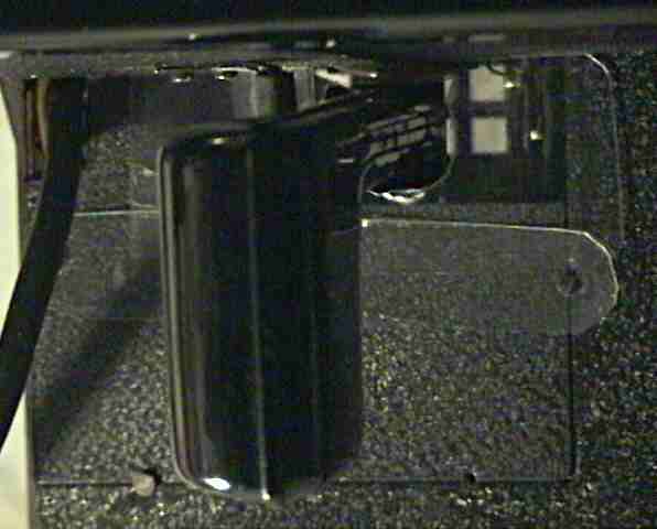
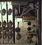
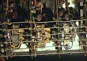
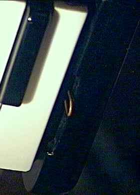
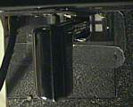 Through
the knee lever hole it was extremely easy to touch the highvoltage electronics
of one of the tone generators; I am not sure if there ever was a protection
against this (e.g. in form of a latex rubber bellows that disintegrated
over time by oil/ bad treatment, or a brittle bakelite board that broke
and thus was thrown away) or if in 1950th they really never cared about
children safety. I covered it with transparent sheet plastic to prevent
electric shocks. (At the left corner is the hole of the power supply/ amplifier
cable.) Through
the knee lever hole it was extremely easy to touch the highvoltage electronics
of one of the tone generators; I am not sure if there ever was a protection
against this (e.g. in form of a latex rubber bellows that disintegrated
over time by oil/ bad treatment, or a brittle bakelite board that broke
and thus was thrown away) or if in 1950th they really never cared about
children safety. I covered it with transparent sheet plastic to prevent
electric shocks. (At the left corner is the hole of the power supply/ amplifier
cable.) |
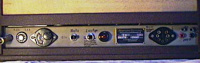
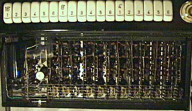
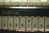
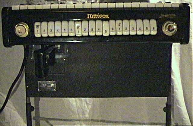
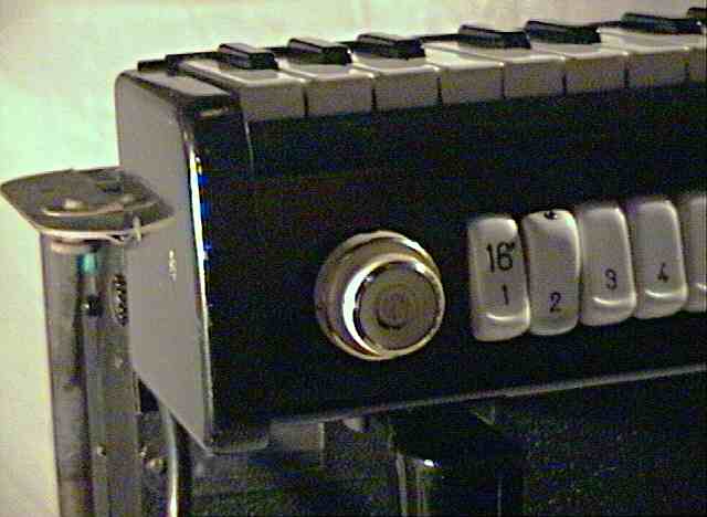
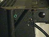 There
is a mystery pair of jacks and the left side. The black knob controls pitch
in a very limited range. At the right side is a similar knob for the preset
volume control (in opposite to the knee lever volume). There
is a mystery pair of jacks and the left side. The black knob controls pitch
in a very limited range. At the right side is a similar knob for the preset
volume control (in opposite to the knee lever volume). |
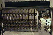
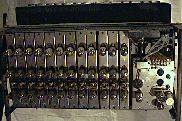
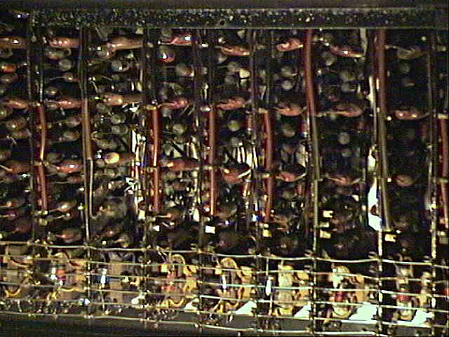
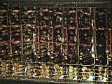
This is the back of the organ with cover cage removed. |
 |
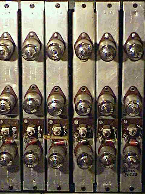
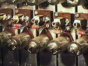
There are 12 oscillator modules; each produces one tone of the octave
and contains 3 tubes for the 3 octaves of the instrument (top is the lowest). |
 |
To tune the organ, this row of trimmers can be adjusted with a screw
driver.
As it came, the tone scale sounded quite detuned (especially the "h");
I am not sure if this is due to broken capacitors (the main oscillators
seem to use less prone plastic ones) or if this Tuttivox was intentionally
tuned like an ancient church organ. (I read that also Arp Schnittger pipe
organs etc. often used much different tunings than the modern well tempered
scale.) The POKEY composition "One Man and his Droid" (available on the
SAP Atari XL music archive) can be played almost perfectly with this scale,
but most normal music sounds a bit strange. |
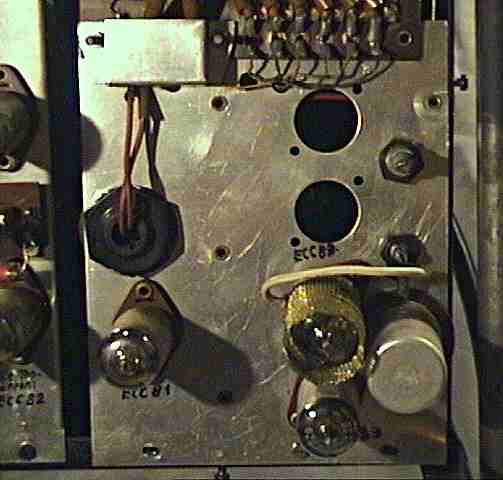
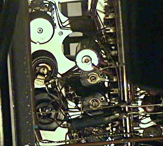
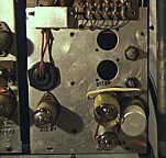
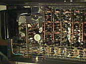
 To
the right is the pre- amplifier and vibrato unit of the organ. At its right
side are 2 trimmer potentiometers; the upper one limits the maximum volume
of the organ. (Mine came fully cranked up, but I guess that is was originally
built in to prevent kids from playing too loud.) To
the right is the pre- amplifier and vibrato unit of the organ. At its right
side are 2 trimmer potentiometers; the upper one limits the maximum volume
of the organ. (Mine came fully cranked up, but I guess that is was originally
built in to prevent kids from playing too loud.) |
 |
 |
 |
Here you see the custom made special potentiometer of the knee lever.
As expected, the uncovered, dirt prone wiper contact causes some crackling
noise when moved. |
 When
we remove the front cover, we can take a look at the heart of the instrument... When
we remove the front cover, we can take a look at the heart of the instrument... |
 |
 |
|
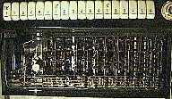
It must have been a horrible lot of work to solder all these components
together. I have no clue how expensive this small instrument was, but I
could well imagine that it costed as much as a grand piano. Unfortunately
the fully electronic tone generators contain several dozens of "explosive
candy" capacitors, and most of them already have more or less cracks in
them. Unlike the solid construction of my Tektronix tube oscilloscopes,
the 3 dimensional structure of this hardware is rather awkward to maintain,
because it consists mainly of brittle, traceless Pertinax circuit
boards those are faithlessly bolted and soldered together without removable
connectors. Also the selection of components looks rather like a collection
of post- war shelf mess than produced by a single factory.
 |
 |
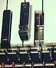
Beside the 2 trimmer potentiometers mentioned above, there are 3 further,
black trimmer pots simply hanging on their bare, flimsy wires among components
at a circuit board. It must be a more than unpleasant and challenging task
to adjust these during operation, because the smallest mistake can cause
things to bend, short and burn out, or makes you slip with your (hopefully
gloved) hand or screwdriver into the high voltage electronics. |
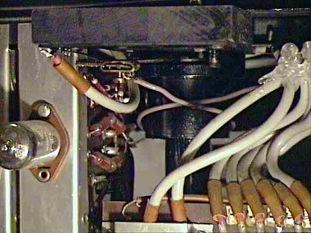
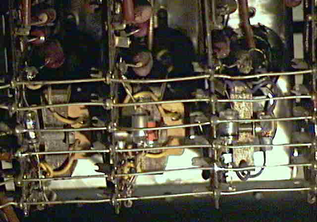
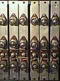
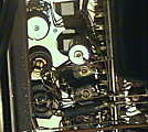
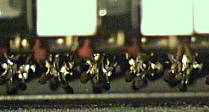
 Every
tone generator module contains a small transformer (generating a 4th octave
overtone?). The modules are connected at the bottom by a main bus rail. Every
tone generator module contains a small transformer (generating a 4th octave
overtone?). The modules are connected at the bottom by a main bus rail. |
main bus pinout: (top to bottom)
-
+297V DC
-
pitch pot (+136..175V DC)
-
vibrato envelope (about 2V AC, stabilized by a big "explosive
candy" cap against GND)
-
GND
-
32V AC
-
0V (?)
|
Even behind the tab switches are multiple such small transformers and
further "explosive candy" caps. |
When I examined the electronics, once the organ smoked badly and made no
sound anymore; I guess I toasted the common pitch control potentiometer
when its resistor at the 2nd bus line was accidentally bent against the
grounded case. After I bent it back, the organ fortunately still works.
 Behind
the keys are lots of small resistors. Behind
the keys are lots of small resistors. |
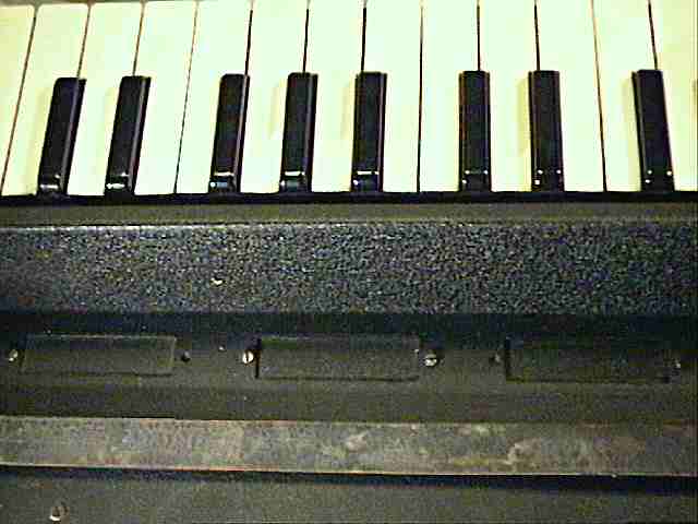
 Here
you see the metal lever under a key, which plastic end presses down 3 spring
wire contacts. Behind the keys are the springs those hold them up. Here
you see the metal lever under a key, which plastic end presses down 3 spring
wire contacts. Behind the keys are the springs those hold them up. |
 At
the right keyboard end is a small wire lever to clean the key contacts. At
the right keyboard end is a small wire lever to clean the key contacts. |
The leaf springs those hold keys up have all different strengths - I don't
know if this is because it was a post- war product or because someone incompetently
tried to fix stuck keys. (Initially mine had a few stuck keys, but the
reason were bent metal levers and not too weak springs.) On the bakelite
keys are many scratches; I guess that someone incorrectly stored the collapsed
stand upon the keys when he transported the organ in its wooden carry case. |


 Behind
the keyboard is a row of 3 pre- punched openings those likely were intended
for an expansion unit (with a 2nd keyboard??). Also the case shape looks
like designed to place another device upon it, although on the internet
I also found info that the similar shaped case of the Clavioline
was designed to be mounted with its rear end under the keyboard section
of an acoustic piano.
Behind
the keyboard is a row of 3 pre- punched openings those likely were intended
for an expansion unit (with a 2nd keyboard??). Also the case shape looks
like designed to place another device upon it, although on the internet
I also found info that the similar shaped case of the Clavioline
was designed to be mounted with its rear end under the keyboard section
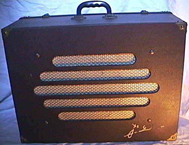
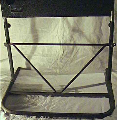
of an acoustic piano.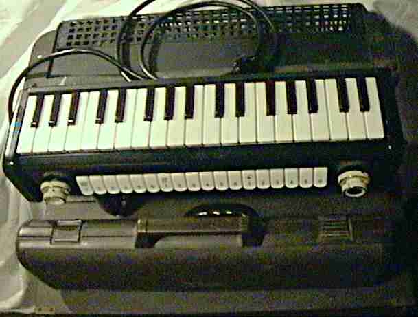 For
a size comparison you can see here my 1980th Yamaha
PortaSound PS2 in its carry case on top of the 1950th Tuttivox
amp.
For
a size comparison you can see here my 1980th Yamaha
PortaSound PS2 in its carry case on top of the 1950th Tuttivox
amp.