| Dübreq
Stylophone 350S |
stylus operated simple synth with light sensor and VCF |
|
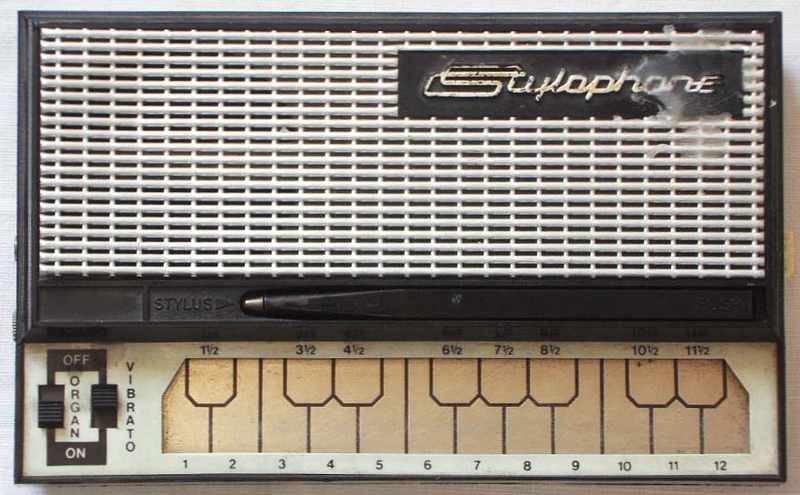
The Stylophone 350S is a British stylus operated monophonic squarewave instrument made in 1971. It layers 4 switchable partials (footages) and a square LFO can toggle between 2 notes or chop the tone and there is an attack switch. Most interesting is the light sensor for modulating wah-wah or vibrato depth.
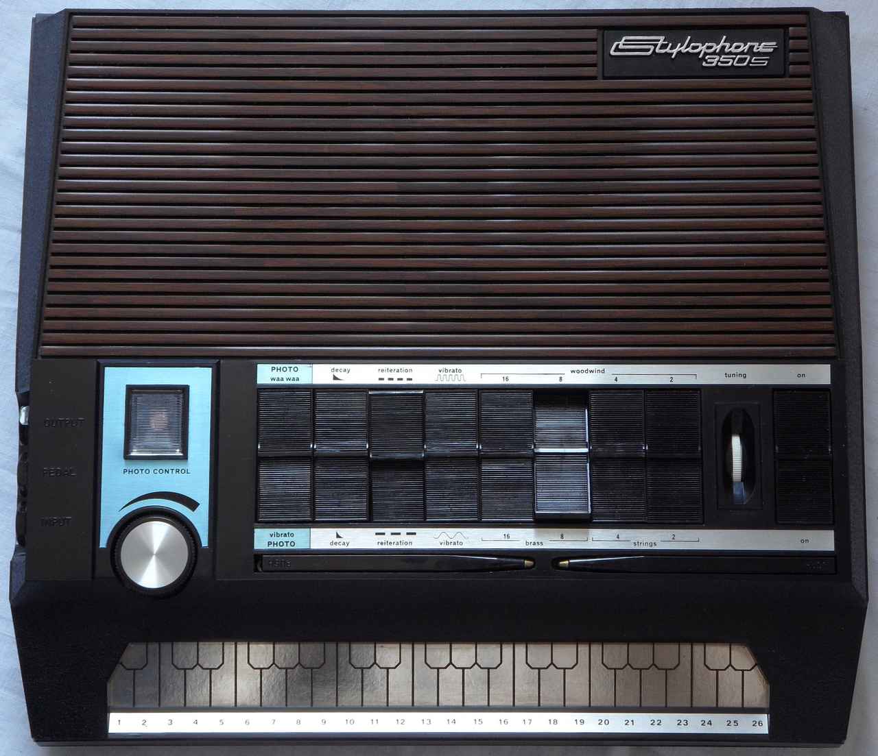
Beside the longer keyboard, the 350S falls in a similar category like a Gakken SX-150 or Korg Monotron mini analogue synth, thus do not pay too much. This is rather a rare toy than serious instrument, although it is fun to play. Especially people should not fall for the false myth that it is duophonic (2-note polyphonic). The only thing it can do is to alternatingly toggle its monophonic VCO between the notes of both stylusses at a fixed speed (like the dumbest possible arpeggiator), and even this only so long one stylus stays to the right (on a lower note) of the other. I particularly don't understand why Dübreq used these stupid rocker switches for setting each only 2 speeds for decay envelope, vibrato and "reiteration" (chopper or toggle mode - unlike mandolin ring at least mine does not decay). I definitely would prefer here each a potentiometer + on/off switch, which would have taken not more space. (Likely in 1970th "preset" switches were believed to be easier for novices.) The 350S also seems to be the only monophonic instrument with a drawbar IC for 4 footages.
Despite the 350S contains 2 LFO (for vibrato and chopper), some kind of (LC based?) VCF and even a light sensor (for volume, vibrato depth or cutoff) it IMO lacks many features (e.g. attack rate, pitchbend, modulation matrix, combining both stylusses differently, additional ribbon controller) I would expect in a basic monophonic synth.
 Danger!:
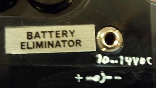
Do not feed it with 18V; it wears and can eventually destroy ICs. 10 to
max. 14V DC is way enough. An "offical" instrument refurb website spreaded
hysteric warnings for selling overpriced snakeoil against sudden death
of an allegedly "irreplaceable" vintage amp IC. In real life any cheap
regulated 12V power supply (center pin positive) is all you need to run
it safely. Also a DIY battery adapter should have only 12V in total (both
sides are in series, hence each 6V).
Danger!:
Do not feed it with 18V; it wears and can eventually destroy ICs. 10 to
max. 14V DC is way enough. An "offical" instrument refurb website spreaded
hysteric warnings for selling overpriced snakeoil against sudden death
of an allegedly "irreplaceable" vintage amp IC. In real life any cheap
regulated 12V power supply (center pin positive) is all you need to run
it safely. Also a DIY battery adapter should have only 12V in total (both
sides are in series, hence each 6V).
Interesting is that the technical concept has many similarities with the Clavioline (a compact monophonic tube organ with vibrato, timbre switches and in some models mandolin-like effects, that was widely used in 1950th). Perhaps Dübreq's original idea was to create a solid state miniature version of it.
 |
 |
 It
would be interesting how far a cheap common Stylophone can be hacked
to simulate its features. E.g. the "reiteration" stylus likely only needs
a squarewave LFO that connects a 2nd stylus to the stylus input (high resistance
during pause). Envelope stuff and wahwah may be simulated e.g. with guitar
pedals. The efficient 3 transistor hardware of Brian Jarvis first generation
Stylophone of 1968 feels like an educational example or experimentation
kit design. It's like a Japenese "boys radio" (websearch it) made from
2 transistors. As a kid I had a "Super Charlie" toy organ with similar
circuit. Until mid of 2000 the Chinese company Yongmei sold their
infamous transistor tooters, those still contained very similar hardware
(sometimes with additional greeting-card-grade demo melody IC) in a mockup
case of midsize or even fullsize keyboards of atrociously flimsy plastic
(see Golden
Camel 7A).
It
would be interesting how far a cheap common Stylophone can be hacked
to simulate its features. E.g. the "reiteration" stylus likely only needs
a squarewave LFO that connects a 2nd stylus to the stylus input (high resistance
during pause). Envelope stuff and wahwah may be simulated e.g. with guitar
pedals. The efficient 3 transistor hardware of Brian Jarvis first generation
Stylophone of 1968 feels like an educational example or experimentation
kit design. It's like a Japenese "boys radio" (websearch it) made from
2 transistors. As a kid I had a "Super Charlie" toy organ with similar
circuit. Until mid of 2000 the Chinese company Yongmei sold their
infamous transistor tooters, those still contained very similar hardware
(sometimes with additional greeting-card-grade demo melody IC) in a mockup
case of midsize or even fullsize keyboards of atrociously flimsy plastic
(see Golden
Camel 7A).
The light sensor needs bright light to respond well, thus I recommend
to play it with the small LED flashlight OR hand-mounted lamp that can
be covered by fingers for full modulation depth. A blinking light can be
used as LFO. Also a glove with finger contacts instead of a stylus may
be used for play tricks.
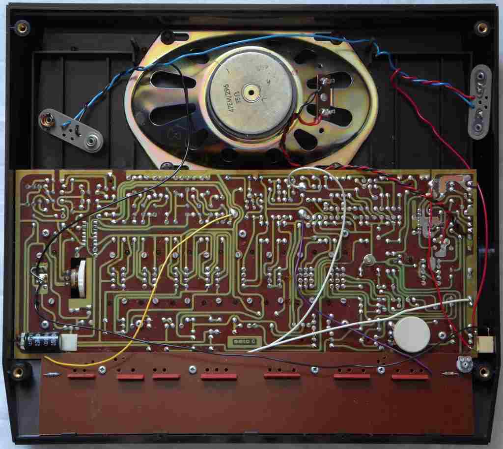
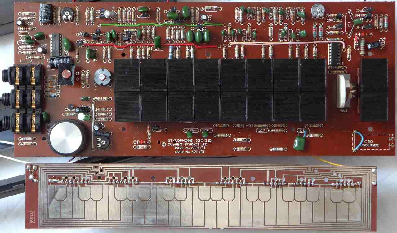
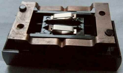
hardware detailsThe Stylophone 350S is built around a top oscillator driving an octave divider IC and plenty of discrete circuits for LFO, VCF etc. The parts vary with hardware revisions. Mine uses as octave divider the CMOS 7-stage ripple counter "Motorola MC14024BCP" and the power amp IC (mine is "National Semiconductor LM380N").
On Youtube I found a Stylophone 350S teardown and repair video by Marco Reps, that shows yet another chipset version (revision "6510 B"?). His (already replaced?) amp IC SN76018 had a SIL pinout and he has reverse-engineered some of the ciruitry (showing schematics). He didn't answer e-mails, but in his video he told that a shorted capacitor killed his amp IC, so he rewired it to a TDA2030. Also his different rocker switch type (with wiping contact) does not seem to fall apart when removed from the PCB. Stylophone 350s Vintage Synthesizer - Teardown, Repair, Reverse Engineering
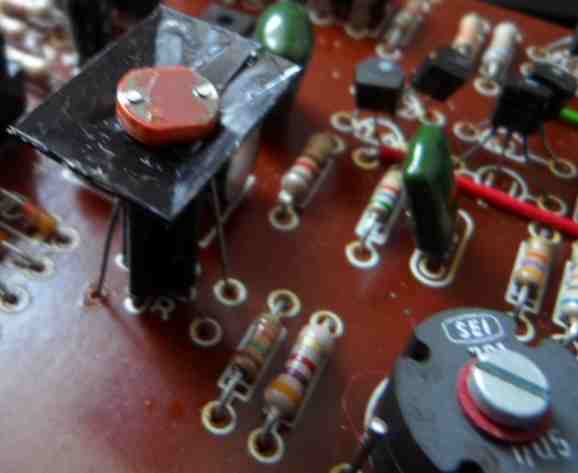
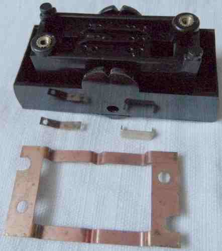
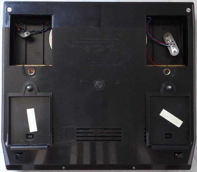
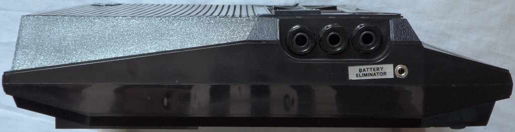
My octave divider is the CMOS 7-stage ripple counter "Motorola MC14024BCP, M 9 38" (14 pin DIL) as the octave divider. It is basically a flipflop chain that halves the VCO frequency in each step. My power amp IC is "National Semiconductor LM380N, /925" (14 pin DIL). Despite the 2 huge 9V battery compartments this model can run very well on 10V (tested with halfway empty 9V transistor batteries). Both batteries are wired in series (no intermediate tap) for supposed 18V, and there is also a 3.5mm power supply jack (labelled "BATTERY ELIMINATOR", positive center). I strictly recommend to feed it with not more than 10V to 14V DC ("6V" or "7.5V" setting of unregulated PSU) to avoid damage. The foam rubber on battery lids were very crumbly and fell apart by any small touch, thus I had to vacuum the residues out. Also 2 Piher trimmers had strange white blooming (like mould fungus) on them that could be easily wiped off; may be the plastic sweated out some chemicals. This may be by battery leak vapours, but another Piher pot looked ok. The volume pot is made by ITT with white plastic package.
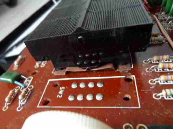
Strange is that (seen in revision "6510" and "6510 C") at one side of the "reiteration" switch the trace shorts all 4 contacts (making that contact useless) in a strange curly shape that looks like when originally the lower contact was designed to be separate and changed later to fix a bug. important: reduce operation voltage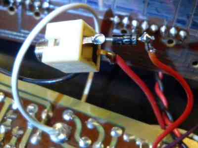 After
I got the instrument to work, I installed a polarity protection diode (will
also reduce voltage by 0.7V). Do not operate this instrument on 18V, which
can destroy ICs! Mine runs well on 10V. Even switching to 8.9V during operation
works, but it can not start that low (possibly a low battery detection).
My unregulated power supply makes it hum a bit. Thus particularly for owners
of the older version with the delicate "Motorola MFC6070" amp IC I recommend
to install an additional voltage regulator. E.g. a 7812 makes 12V output;
if this is not enough for it (my newer model runs on 10V) you may install
one or more diodes in series with the GND (reference) pin of the regulator
to increase the output voltage. After
I got the instrument to work, I installed a polarity protection diode (will
also reduce voltage by 0.7V). Do not operate this instrument on 18V, which
can destroy ICs! Mine runs well on 10V. Even switching to 8.9V during operation
works, but it can not start that low (possibly a low battery detection).
My unregulated power supply makes it hum a bit. Thus particularly for owners
of the older version with the delicate "Motorola MFC6070" amp IC I recommend
to install an additional voltage regulator. E.g. a 7812 makes 12V output;
if this is not enough for it (my newer model runs on 10V) you may install
one or more diodes in series with the GND (reference) pin of the regulator
to increase the output voltage.
But the big warning on the official Stylophone 350S sales website (and the many websites copying from it) IMO sounds very much like propaganda to raise panic for selling expensive snake oil (like the "Stylophone ACM" module upgrade voodoo) for the sheer sake of moneymaking. Even owners of a 1st generation Stylophone 350S can certainly easily buy a cheap regulated 12V power supply to operate it without any risk of damage. Also installing a chain of about 5 1A silicon diodes (e.g. 1N4007, each dropping 0.7V) in series with the battery is a cheap and simple measure to reduce the operating voltage by >3V, which should be enough to keep the MFC6070 in its safety margin. I even doubt that the instrument is that ultra-rare; may be that Dübreq only counts their nowadays customer list as the total number of owners. Unlike modern digital instruments, there are no unreplaceable special parts (ASIC, SoC, chips with firmware, displays etc.) inside, thus so long it looks mechanically reasonable, any broken 350S can be fixed by adapting standard parts. theory of operationDuring repair I quickly measured the hardware with my analogue oscilloscope. The octave divider IC derives from the VCO squarewave undertones , those are mixed through 4 switches (with different capacitor filter on both ends).The key contacts respond on connection to GND (that is what the normal stylus does), which triggers the decay envelope (if enabled) and plays a tone with pitch depending on the resistance of that connection (much like Gakken SX-150; due to their wiring as a resistor chain, pulling multiple "keys" to GND makes the higher note succeed). With "reiteration" (chopper) enabled, the reiteration stylus apparently pulls to GND through a pulldown transistor modulated by a square LFO. Because the other stylus stays always GND, using both together makes the tone only toggle between notes when the normal stylus is on a lower note (a multivibrator with 2 real toggling stylusses would have prevented this). To prevent waiting on a note, the chopper LFO starts only when its stylus touches the keyboard. AFAIK no other Stylophone used this kind of dual-stylus mode. But the method how they are connected through a square LFO can be likely retrofitted to upgrade any cheap standard model. For professional circuitbending the 350S has high potential. Because everything is analogue, potentiometers may be installed as drawbars or to change the LFO and decay speeds. Connecting a capacitor to GND at the decay switch makes slow attack. The LFO signals may be also routed elsewhere. Strange is that vibrato (intentionally?) fades in very slowly when the switch is pressed. |
Successors with analogue synth features are the Stylophone Gen X-1
and Gen X-2, but none have dual-stylus mode nor the longer keyboard
of the 350S.
| removal of these screws voids warranty... | ||
 |
||
|
|