|
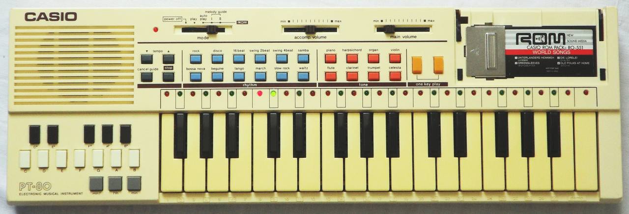
Like the Casio PT-30, the single finger chord concept of this instrument makes chords selectable by name instead of pressing multiple keys, but unlike the latter it is even more restricted and permits only 4 different chords. Besides the white version, this instrument was also made in red. A silver grey French version was made as Liwaco LW-640. The original German retail price of the PT-80 in a German Conrad catalogue from 1986 was 299DM (about 150€).
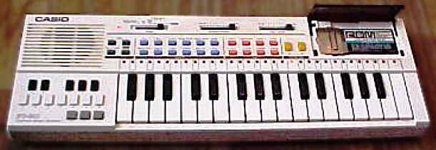
(old eBay photo) |
 |
 |
 |
Although the single finger chord section looks interesting, its capability is very restricted; during rhythm the organ chord is always replaced by automatic accompaniment (like with most keyboards) and it is also generally impossible to play fewer or different tones than a standard 3 or 4 note chord, and unlike the PT-30, this instrument even plays only 4 different chord types and nothing else. With rhythm, once the accompaniment has started (by touching a chord key button), you can not stop the accompaniment again (i.e. pause chords) without stopping also the rhythm.
Rhythms are selected by OBS buttons, and by pressing the button of the already playing rhythm, a fill-in is inserted. The analogue rhythms resemble Casio PT-30, but additionally they have an unusual popping snare drum, that sounds like an exploding firecracker far away. The percussion has an interesting timbre with partly long sustaining white noise "cymbals". The congas are based on squarewave tones produced by the CPU and muffled by external capacitors.
The instrument was sold with the Casio ROM- Pack RO-551"World
Songs", which contains the 4 songs {1= "Unterlanders Heimweh", 2="Greensleeves",
3="Die Lorelei", 4="Old Folks At Home"} and has a "not for sale" notice.
All these musics have a great and complex orchestrated arrangement.
The ROM- Pack cartridge employs the same conductive carbonized silicone
rubber connector that is used in many LCD watch displays. More interesting
is that the musics from it can be used with "melody guide" training
feature, in which a flashing LED (next key) and a lit LED (current key)
in the LED chain above the keys teach monophonic keyboard play. It has
2 training levels {1= keeps playing, 2= waits for correct key}. With the
"cancel guide" button the LED row can be switched off, thus the same 4
variants like on the later Casio PT-82
exist. But the PT-80 does neither include the great "rating" feature of
the latter. When the instrument is switched on, it plays a tone scale (8
notes) while a light runs from left to right on the LED chain.
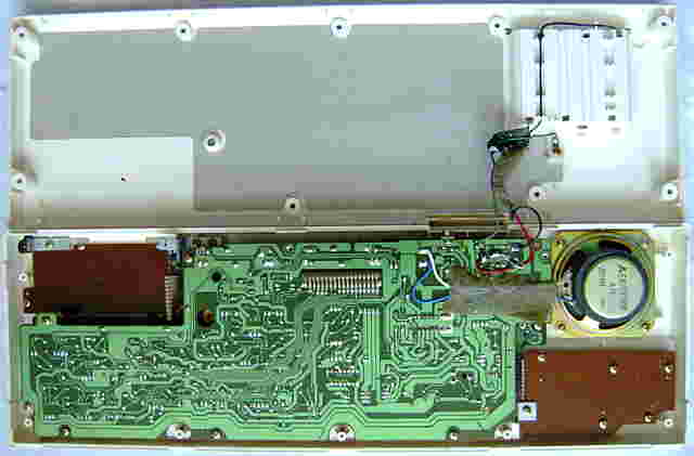
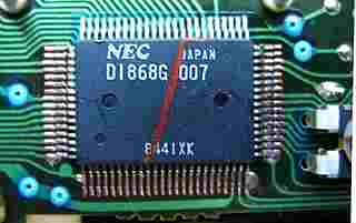
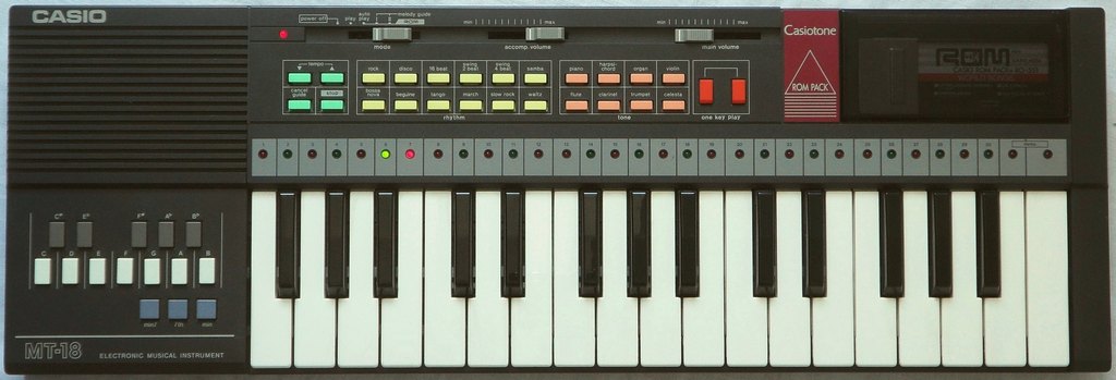
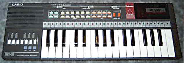
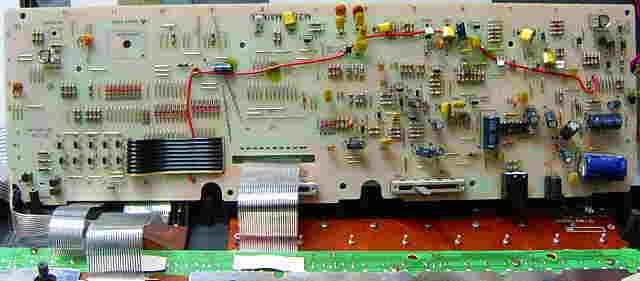
hardware detailsThe Casio PT-80 was a cheap monophonic keyboard with ROM-Pack slot, based on the single chip CPU "NEC D1868G 007". A midsize version (with different PCB layout) was Casio MT-18.
multipulse squarewave & timbre filter The digital part of the sound generator is almost identical with Casio
PT-50 (see there). The main voice is routed through a fixed timbre
filter, which is controlled here only by CPU output 68 'O4' (highpass),
so it has only 2 settings. Pin 67 instead switches the cymbal/hihat envelope
decay duration (hi=long).
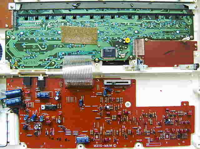
The accompaniment bass voice is plain 1:1 squarewave that is alternatingly output with the chord and muffled by a fixed filter. Additionally to the normal drums, the PT-80 contains a loudly banging analogue snare triggered by CPU pin 32. keyboard matrixThe piano keys and preset sounds are wired almost like in PT-50, with the difference that there is the additional C4 key. It took me long to find out that the pin order of KO6 and KO7 are swapped (seen in schematics) and hence my analysis did not match the PT-80 service manual. Also the 'one key play' and 'temp' buttons are confused in its depicted matrix layout (but correct in schematics), but that manual is generally quite buggy and even lacks layout of the digital PCB (mainboard). (I found no eastereggs.)
The input lines are active-high, i.e. react on +Vs. Any functions can
be triggered by a non- locking switch in series to a diode from one "out"
to one "in" pin. The key leds are multiplexed from the matrix output pins
{10..20} to pin {69..71} through 11 transistors.
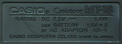
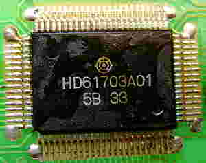
pinout D1868G, HD61703The LSI "NEC D1868G xxx" / "Hitachi HD61703xxx" (80 pin SMD, pins count anticlockwise, xxx = software number of internal ROM) is the CPU of cheap Casio mini keyboards with optional ROM-Pack port. It outputs multipulse squarewave waveforms on individual pins for monophonic main voice, monophonic obligato voice and a 4 note chord+bass. Each of these have an additional pin with coarse digital envelope (strong zipper noise, 10 stair steps?) those need to be combined in an external VCA (transistor circuit). Only the blip percussion (made from plain squarewave of several pitches + shift register feedback noise) already contains a 3-bit(?) logarithmic decay envelope in its output signal. The CPU can control key lighting LEDs (through key matrix outputs and 3 additional pins, using transistors) and has an LCD output. It is clocked by an LC oscillator with tuning trimmer; unlike modern keyboards, the clock can be stopped and continue from there, thus it is fully static without DRAM.By its main voice sound engine this is the direct sucessor of the D1867G CPU in Casio VL-1, but percussion engine and other features differ. So it is way less calculator-like; the D1868G does not need 3V (that was obviously designed for one lithium or 2 alkaline button cells) anymore, and none of the versions contain a pocket calculator nor ADSR synth (that was using its "M+" memory and number entry method). While the PT-80 has a "NEC D1868G 007" CPU, its case variant MT-18 contains a "Hitachi HD61703A01" with same functionality. Also the wiring of both looks the same, which strongly hints that HD61703 is identical or successor of the D1868G found in earlier and more complex mini keyboards like PT-50 and PT-30, those had sophisticated sequencers with LCD display and datasette storage. Despite the digital melodic drums always contain a grainy digital envelope, most versions add an external filter. In PT-80 the additional analogue snare has its own trigger pin and mixes some digital white noise from the CPU into its transistor circuit, and the main voice has 2 filter settings (lowpass, highpass). PT-30 and PT-50 apparently contain a similar snare (with softer timbre), and have a cymbal trigger and cymbal envelope shorten output; their main voice filter has even 4 settings. Later toy keyboards like PT-82 and EP-20 had very simplified hardware without external percussion envelopes and a poor sounding digital snare (noise modulated squarewave). Unlike in Casiotone 201, the unconnected LCD port of HD61703B01 (Casio PT-80, PT82) seems indeed unused; while pins {39..41} have characteristic multi-step waveforms, the pins {42..66} output an identical steady squarewave of some kHz. None of these ever change (as far my analogue scope can tell), thus likely there was no control software included in this cut down toy. But the existence proves the relationship with the older D1868G. In PT-80 schematics the CPU is labelled µPD1868AG-007 / µPD1868G-007, which hints that another alternative name may be D1868AG. Its ROM-Pack port is wired 1:1 to CPU pins 33..23. In PT-30 the SRAM "Hitachi HD61914B"
uses almost the same pinout like a ROM-Pack,
but has 3 additional pins 14, 17, 19 multiplexed with keyboard matrix and
datasette port. In PT-50 the wiring is more complex to handle 2x SRAM +
ROM-Pack + datasette.
By the lack of schematics, I first had made an EP-20 pinout (like PT-82) from my own observation. Later I filled the rest and identified pin names from the Casio PT-80 service manual. The PT-82 hardware has simplified digital blip percussion and no switchable filter. In PT-50 service manual the pins 10..20 are named KC instead of KO. Of Casio KX-101 I only have incomplete schematics without pin description. caution: The PT-80 service manual indicates that this CPU uses
"negative logic", i.e. technically +5V is its GND while 0V is its -5V supply
voltage. So the voltages are not was the pin names suggest. I use
the positive voltage naming convention (from 0V to +5V, not -5V to 0V).
Strange is that in this CPU only the keyboard matrix output pins 16 KO6 and 15 KO7 are in reversed order (seen in PT-80 schematics), which is consistent with the matrix layout of all related instruments. The white noise pin 72 (verified in PT-80) changes frequency with clock rate and thus is digital (shift register feedback) and not transistor noise. In my Casio EP-20 (PT-82 hardware) the power switch connects pin 1 through a capacitor to GND when off and to +Vs when on. I measured +Vs=+4.6V (batteries half empty). Pin 21 makes the CPU (leds and power amp) wake up for a fraction of a second when it detects a positive pulse. There is a capacitor from pin 30 to +Vs, that with other keyboards is inside the ROM-Pack. Pin 72 outputs a hiss that may be shift register feedback noise. Pin 73 goes high (turns power amp on) while the instrument is on. Pin 77 may be meant as obligato envelope, but I measured the complete audio signal here; possibly it crosstalks from the external VCA. Pin 35 is high resistance with some strange HF dirt waveform on it; the PT-80 service manual shows here a rectangular snare trigger pulse, that was likely omitted by software. Pin 67 in EP-20 behaves like an analogue DC voltage input that reduces the main voice volume. (You may wire it through a 330 ohm resistor in series to a potentiometer against +Vs. But I consider it safer to wire a channel volume pot as voltage divider at pin 79 or 80.) At about 330 ohm it fully mutes. Do not input more than about +1V or use a lower resistor; already at 320 ohm the current is 10mA high, which may cause long-term damage to the CPU. The output amplitude of pin 80 changes very little (bottom level slightly shifts up). It turned out that also in this model pin 67 and 68 are filter control outs, those are here always the inverted of each other, hence pulling both high likely muted both signal paths of the analogue filter circuit and so reduced volume. In PT-80 pin 67 outputs an envelope duration control signal that is lo during cymbal and hi during hihat to shorten it. (In PT-30 and PT-50 the same is apparently done by pin 70.) There are 2 adjacent unused solder pads to pin 9 and 21 in EP-20 those look like a jumper or omitted capacitor. But bridging them only makes the CPU keep resetting (power led flashes) or (with capacitor) not start at all. In PT-50 (like also PT-30) apparently all LCD pins can output a 4 level waveform {0V, 1.2V, 2.7V, 4.2V}, which makes it questionable whether pins 39..41 are specialized "lcd common" outs. Unlike VL-5 it needs no external reference voltage resistors for this. In PT-80 and PT-82 only the LCD pins 39..41 output the 4 level waveform, while pins 42..66 output all the same plain squarewave, which likely means that they contain no software to control a display. In PT-30 bass is output on a separate pin 78 with envelope on 77. Likely because in this first software version ROM-Pack standard was not invented yet, it did not need these pins for obligato channel. Despite analogue post-processing (only a filter?), the drums on pin 74 (like in all other models) already contain a grainy digital decay envelope. Possibly it was originally designed not to need external envelope hardware, but it turned out to sound such poor (as everybody can hear in PT-82) that Casio added it. In PT-30 and PT-50 pulling pin 71 lo mutes all cymbals/ hihats, but does not affect snare. Pulling pin 70 lo turns all hihats into cymbals (or closed into open hihats?) by making them decay slower. The decay rate of a still (slow) decaying cymbal is not truncated (tested in PT-30) when the pin goes hi again, i.e. apparently lo has priority. This pin has no effect on snare, nor on the digital squarewave drums. Pulling pin 69 lo mutes only snare but nothing else. I.e. unlike my expectation, the hiss part of snare is not simply a hihat triggered simultaneous with a dull drum (like done in many cheap semi-analogue keyboards), but has its own trigger pin. Likely it is analogue (using digital noise from CPU pin 72) like in PT-80, but with different sounding circuit. That is to say, pulling pin 72 lo mutes cymbals and the hiss of snare. Because PT-80 has no MT port, pin 35 was repurposed as a trigger out for an additional banging analogue snare (pin 69 is here for LEDs). The reset uses only a 1uF cap from pin 1 to pin 21, but the analogue PCB contains a large unused section for 2 additional ICs (16 and 8 pin DIL) connected to pin 21, thus apparently an early CPU revision or more complex prototype needed a much more complex reset logic. According to the PT-80 service manual, the ROM-Pack port uses CPU pin 27 OP switches (/address, data), 23..26 D4..D1 are the 4-bit data bus, 28, 29 its clock pulses, 32 "ROM pack designation signal" (aka chip select?). Pin 30 VDD2 is an APO out that after 8 minutes without key press changes from lo to hi. Pin 73 does the same but changes from hi to lo. According to PT-50 service manual, pin 22 receives an interrupt to halt the CPU when autoplay has finished. A variant of this CPU is "NEC D1879G 002" in Casio KX-101, which beside accompaniment audio handles a cassette drive with data storage mode. |
A direct successor of the PT-80 was the technically simplified Casio PT-82 (which unfortunately lacks chord buttons and has boring blip drums).
(old eBay photo of my specimen) |
 |
 |
 |
 |
 |
 |
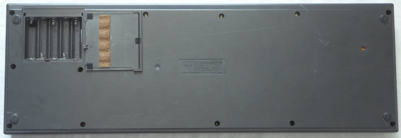
| removal of these screws voids warranty... | ||
 |
||
|
|