 |
 |
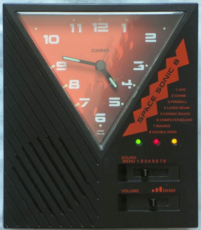
This rare analogue alarm clock has 8 unusual alarm sounds made from short loops of siren-like sci-fi synth noises. Historically most interesting is that the alarm sounds were obviously taken from Casio SA-series mini-keyboards.
|
|
The alarm sounds are short repeating lo-fi synth effects those seem
to be loop samples from those mini keyboards. Ufo is a fluttering siren
tone that goes up and down. Chime resembles an analogue phone ring including
pause. Fireball (downpitched SA-1 "emergency alarm") is a throbbing fast
sequence of 2 alternating low siren tones (very tekkno-like). Laser beam
(faster fragment of that SA-1 tone) is a chopped siren sound with falling
pitch. Cosmic sound (downpitched SA-1 fragment) is a kind of chirp that
varies pitch. Computer sound (downpitched variant of SA-1) is a sequence
of 4 echoing tones. Bounce (fragment auf SA-5 "jumping") is an up
howling tone with vibrato and pauses. Double drop is a kind of fast double
pulse zap tone.
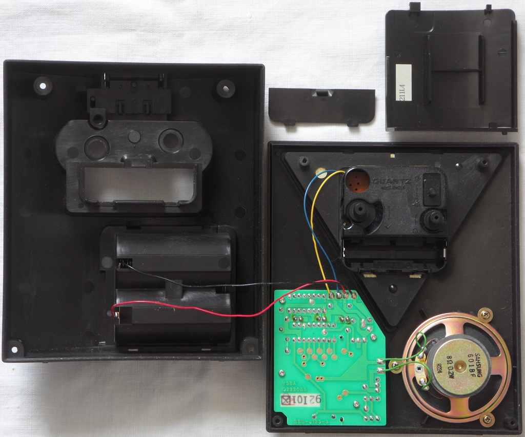
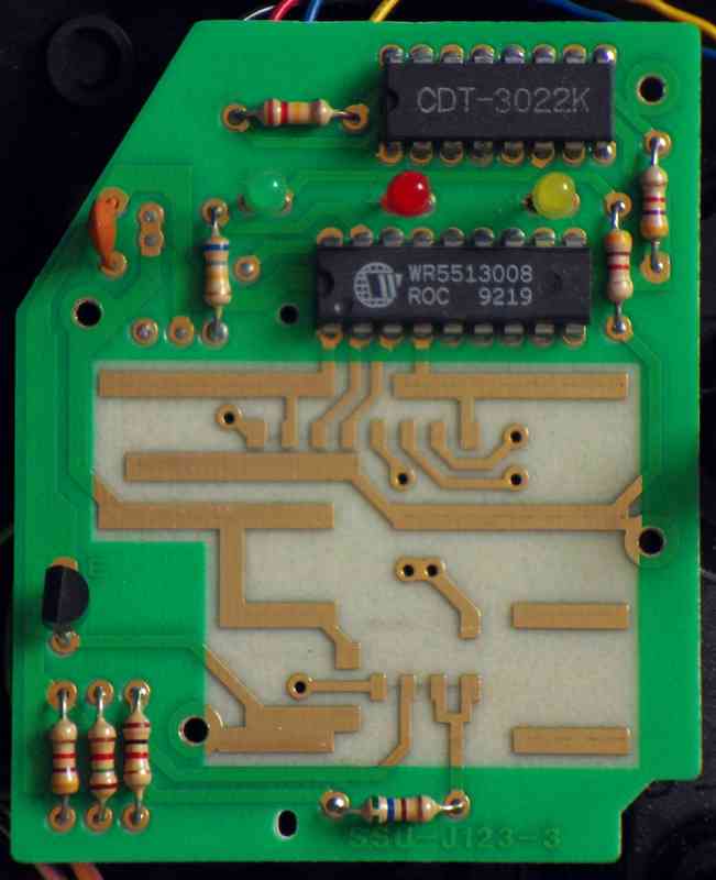
hardware detailsThe Casio TSA-85 is build around the sound IC "WR5513008, ROC 9219" with single transistor amp. A separate IC "CDT-3022K" flickers 3 LEDs.
There is no keyboard matrix. The sound IC simply has one pin per sound that is active-hi, reacting on Vs by a locking switch. Pulling multiple inputs hi starts no sound and also stops sound when it was playing. pinout WR5513008The "Winbond WR5513008, ROC 9219" (18 pin DIL) is the sound IC of Casio TSA-85. It contains 8 short sound loops those simply play so long its corresponding input pin is pulled hi. They seem to be only monophonic loop samples output through its internal 4-bit DAC. But supposingly this is still a microcontroller with internal ROM containing software, because crash behaviour is more complex than expected for such a thing.(Important: By lack of schematics, all pin names were chosen
by me - inspired by the naming convention of the M6387
found in SA-series.)
The low clock rate of only about 66kHz (estimated on analogue scope) proves that despite similar sounds this chip is much simpler than the M6387 of SA-series (which needs 21.725 MHz to implement its softsynth) and also runs on lower voltage. But the 4 test pins show surprisingly complex behaviour, those hint that it is still software based and can be considered a CPU. Lowering the clock resistor (shorted with fingers or 1K) strongly increases pitch and tempo by clock speed until it finally crashes. According to the waveforms on analogue oscilloscope the internal DAC seems to be only 4 bit. For shitshot tests I used a 330 Ohm resistor in series with silicon diode to avoid damage. Pin 11 and 12 apparently output a clock frequency mixed with audio. (The audio may be an analogue artifact due to about 20 Ohm serial supply voltage resistance in the clock alarm contact.) Pin 13 in normal operation does nothing. Pin 10 is interesting, because it outputs hi pulses during the loop point of each sample. Depending on selected sound, these can be one or multiple pulses those may contain the rom address of that sample. Pulling it lo (I used 330 Ohm) bypasses the loop point and so plays multiple samples in a sequence and finally crashes e.g. into a clicking rhythm. (Pulling lo outside the loop point is ignored.) Pulling pin 11 or 12 lo or hi crashes the sound immediately(?). The crashes often include sections of hiss noises those may contain internal rom code expelled through the DAC. Selecting a new sound (through KI pins) in many situations resets the chip (like an NMI) to start normal. Crashes also play sound loops distorted, which may be clipping caused by shifting the DC offset of the DAC (Casio tends to use increments instead of absolute voltage values) . But it may also have a volume envelope register that causes the overdrive. The natural pause in "chime" ends its distortion. Crashes can change loop points and duration (so e.g. cycle through many short fragments of the samples or start at wrong point) but never change pitch and playback speed, which hints that the chip can not control its DAC output frequency but only sample start and end address. Pulling pin 11 hi during power on switches the chip into test mode, in that the KI pins 2..7 and pin 13 output short loops of serial data (seen on analogue scope). Depending on the sound switch position, the patterns on these pins vary or turn hi or lo, which may be usable to dump the internal rom. pinout CDT-3022KThe "CDT-3022K" (16 pin DIL) is the LED flasher IC of Casio TSA-85. It outputs a semi-random flicker pattern for up to 6 LEDs (TSA-85 only uses 3) that lights only 1 LED at once. Apparently the flash pattern can be changed by external wiring. The 6 outputs are open-collector to drive each an LED against 0V.(Important: By lack of schematics, all pin names were chosen
by me.)
The clock rate (estimated on analogue scope, controlle by a resistor) is about 120k. Pin 4 may be the internal tempo clock for the flash pattern. Pulling it lo halts the pattern until release. Connecting it to an LED pin (which pulls it lo) makes it halt when that LED is lit. Pulling pin 2 lo changes the pattern into a walking light that repeats moving only from left to right {yellow, red, green, off}. Pins 9..11 seem outputs for additional LEDs. Pin 15 outputs a weak clock signal and may be a test pin. The unused pin 3 is lo and seems to be an input. Pins 12, 16 seem to be open collector. This chip may have other hidden features I found too boring to examine further. Perhaps it is even simply a logic IC (shift register, binary counter or such) with obfuscated part name. |
A more primitive predecessor of this alarm clock was Casio TSA-80
(seen on Youtube), which 8 sounds employ likely a Holtek soundtoy
chip (monophonic squarewave + noises, LCD game style) like that in Bontempi
- Disney Band Electronic Super Keyboard or the Mini Attacker
keychain toy.
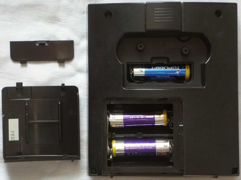
| removal of these screws voids warranty... | ||
 |
||
|
|