 |
|
|
ELECTROPLAY
SOUND
FX
PHASOR
|
|
 |
|
amazing synthesizer soundtoy |
|
|
|
|
|
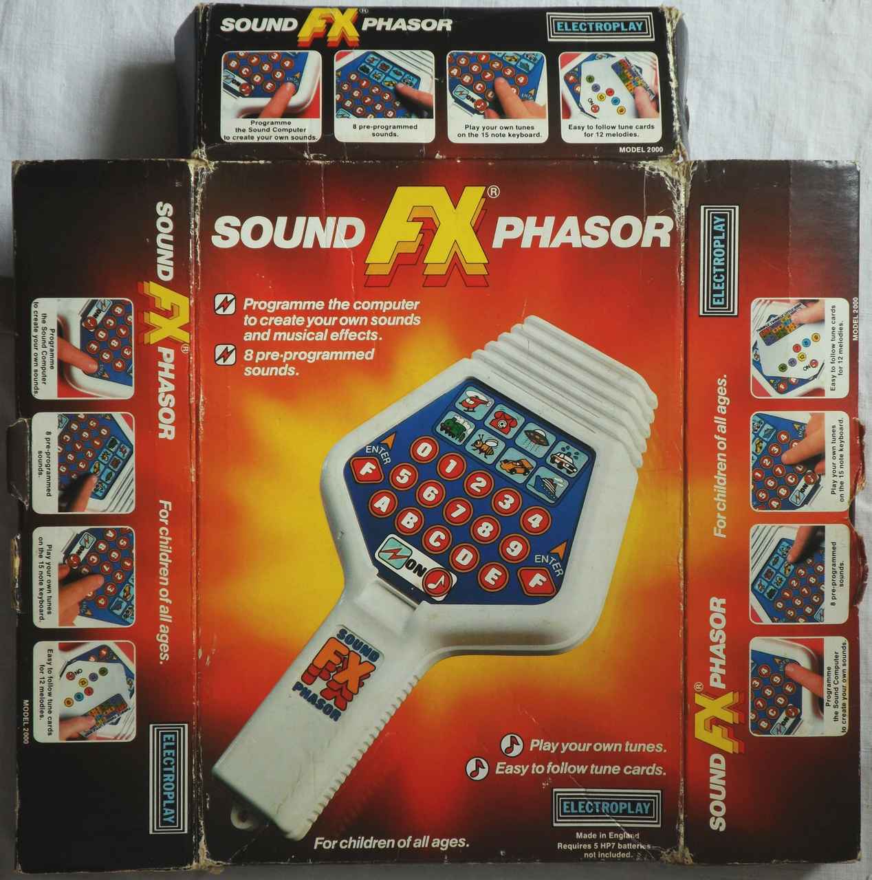
The Sound FX Phasor is a very unusual lo-fi toy synthesizer from 1980
made in Britain by Electroplay. It is historically very important
as the likely world first single-chip softsynth.
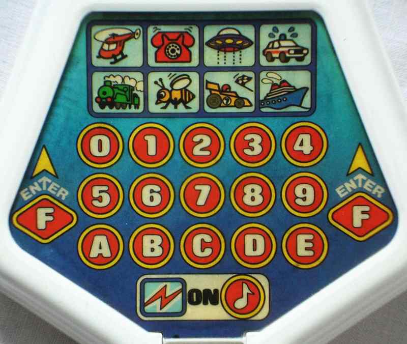
Beside 8 preset effect noises, it has a keyboard mode with synthesizer,
featuring suboscillators with multipulse squarewave and freakish siren-like
howling modulations. Particularly it can do sonorous organ-like bass notes
and crunchy motor noises with simple decay envelope. The foil touchpad
of the monophonic instrument has only 15 "white" keys (no sharps).
Remarkable is that it even precedes the famous Casio
VL-1 by 1 year, and like the latter it can produce a variety of
strange complex sound variants. The grainy lo-fi sound engine employs program
loop synthesis and so may constitute the world first software synthesizer
on a chip. But unlike VL-1 it is more centered on less melodic howling
effects, and often resembles random glitch stuff in the style of Williams
early electronic pinball machines, with strange techno sound loops those
can include crackle, buzz and rough pulsing or bleeping noises. It was
way ahead of its time.
But the user interface is awful. There is no sequencer, synth patches
can not be saved and most obnoxious is that auto-power-off deletes the
created patch (up to 31 key presses) after 46 seconds of idle. As a last
warning it sounds a very low bass note during that you can quickly play
a note to get another 46 seconds. It feels like an unfinished prototype.
The Sound FX Phasor has been emulated on MAME - yet with incorrect
analogue volume envelope, but well enough to give an idea what this obscure
synth unicorn sounds like.
main features:
-
15 foil keys (flats only, no sharps, Octave starts at '3')
-
built-in speaker
-
effect mode with 8 synthesized preset sounds {helicopter, telephone, ufo,
police car, train, bee, racing car, boat}
-
synthesizer mode with 6 parameters (2x pitch envelope, decay, square LFO,
waveform suboscillator, noise waveform)
-
monophonic main voice with grainy lo-fi timbres, complex multipulse squarewave
suboscillator, analogue decay (capacitor envelope PWM), coarse digital
volume envelope and howling digital pitch envelopes. Digital Envelope and
LFO tempo is proportional to note pitch.
-
no volume control
-
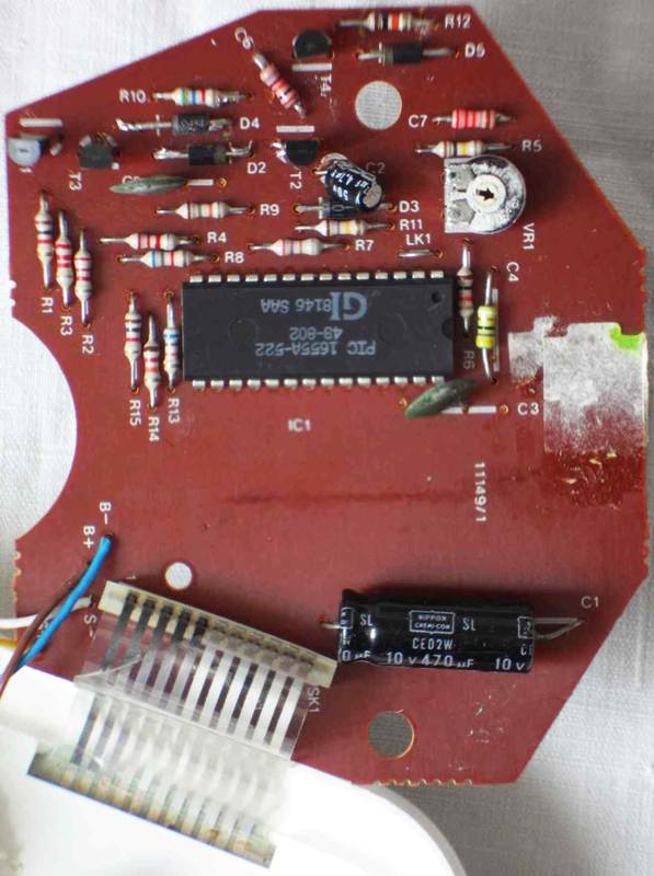
CPU= "General Instruments PIC 1655A-522, 48-802, 8146 SAA" (28 pin DIL
| PIC with 768 byte ROM, 32 byte RAM)
-
auto-power-off (erases memory after 46 seconds)
-
6 cardboard overlays for 12 melodies (I only have 4).
-
no jacks
 |
 |
The manual is a bad joke. |
eastereggs:
-
Switching to synth mode and pressing 2x "F" keeps parts of the last played
sound (e.g. effect noise) in RAM.
-
Typing too long numbers as synth parameter can make glitch sounds?? This
thing behaves so wierd that it is hard to distinguish at all between bugs
and features.
-
shitshot: Undervolting (empty bateries) produce e.g. strange variants of
the effect noises in wrong timbres. They sometimes set off randomly instead
of the APO bass note.
-
disable APO - grounding CPU pin 7 deactivates this worst plague, permitting
to keep the synth patch in RAM.
-
disable keyboard - pulling pin 6 hi turns all keys off.
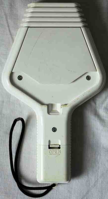
notes:
It is unknown why the instrument handle is equipped with a leash. Did they
really expect it to fall out of hands? This is no pocket digicam for quick
snapshots, and nowadays people tend to type on touch surfaces of much smaller
devices with only 2 thumbs when texting on smartphones. Unlike its name
it barely resembles a Star-Trek phaser. So the strange case shape suggests
that it was originally planned to include something like a barcode scanner
(an at that time popular feature found e.g. in Casio
VL-5 or
TI Magic Wand) to ease synth programming, or internal
microphone as a programmable vocoder/voice changer toy. On the original
box the German text version even refers it a "computer game" despite it
not even contains basic stuff like Simon. Unlike similar toys of its era,
it lacks built-in melodies. On the box it was advertized as a toy for all
ages that can add sound to kid's (non-electronic) silent toys, teach to
play tunes, for youngers to teach shapes and colours, and for olders to
program own sounds on its computer. Inside the handle are 5 AA size batteries.
The cardboard foil touchpad of this instrument looks rather flimsy. It
is not very responsive and notes can have varying latency and need to be
held to play long sound loops, but despite it was designed rather as a
noisemaker and is not that good in imitating acoustic instruments, it works
sufficiently well for making music (particularly as sample source) and
e.g. can make nice buzzy synth bass notes (supersaw style). The 8 effect
noise buttons in its top row are doublets wired parallel with number (note)
keys. During play, the speaker above the touchpad can be muffled by hand
to modulate volume.
The instrument has no volume control, so it always plays at medium volume
(with fresh batteries somewhat loud), but battery life is still ok, which
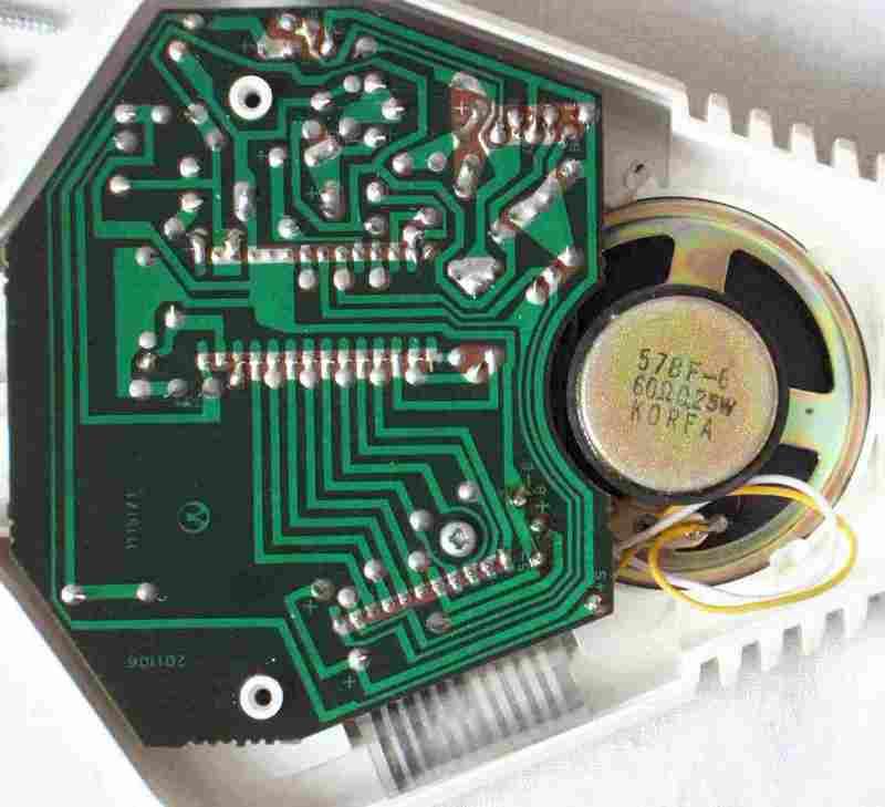
may be the miracle of 60 Ohm speaker. There is no mechanical power switch;
it is powered on by pressing the effect (lightning) or synth (musical note)
button, which sounds a Pong-like rough purring buzz (both have different
pitch). All buttons make sound, which disturbs live performance. Worst
is that after 46 seconds of idle it always powers itself off (sounding
at second 43 a decaying very low bass note), which unfortunately deletes
the currently created synth sound. This is particularly annoying because
it has no display to write it down, typing it in takes up to 31 button
presses (Casio VL-1 needs 9), and the synth programming is not straight
forward and feels more like something circuit-bent and semi-random. Also
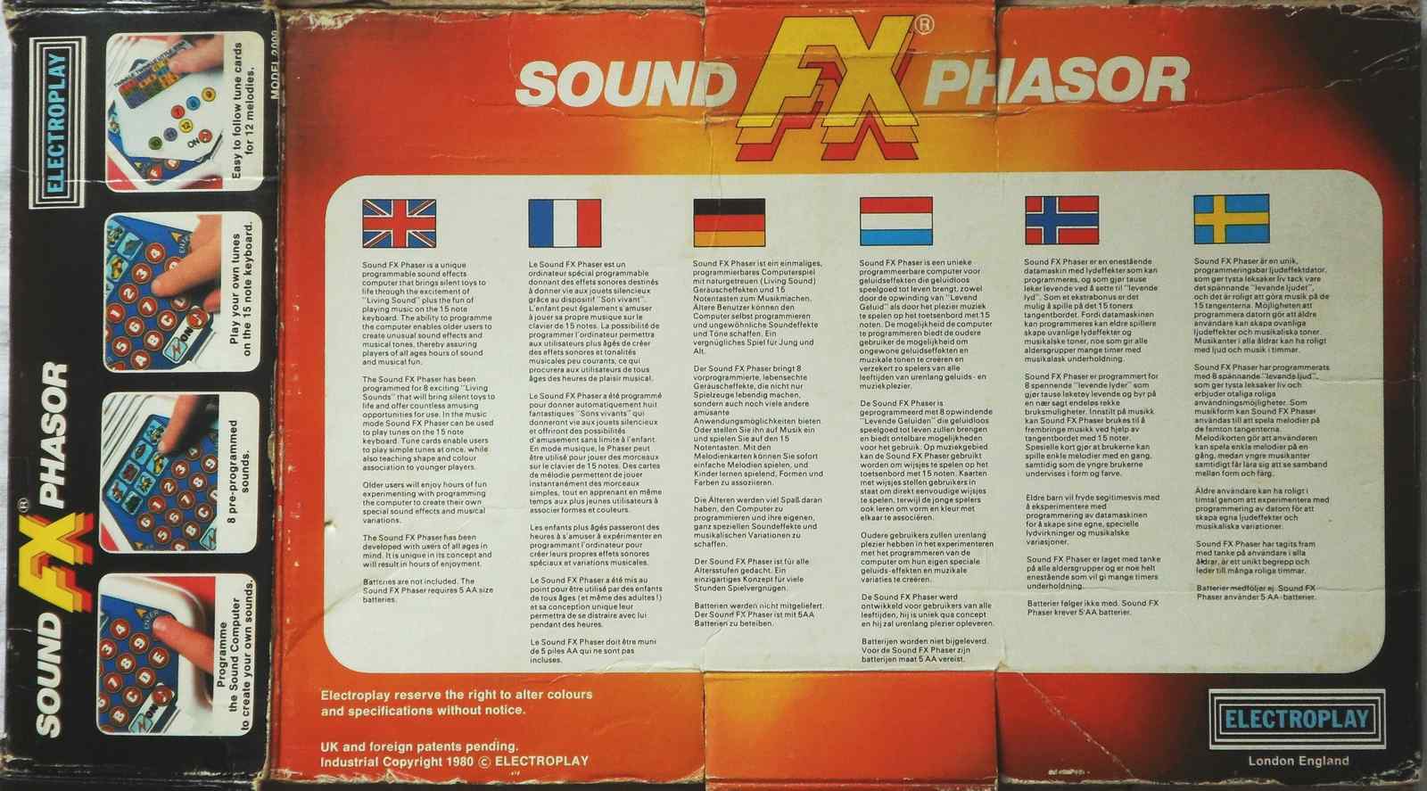
switching to effect mode clears synth RAM. The box has a note "UK and foreign
patents pending. Industrial Copyright 1980 (c) ELECTROPLAY.", but websearching
that name only finds plenty of SM filth; possibly this was only a label
of another company and quickly got changed by the sextoy connotation. A
box tab is also marked "Reedecor", which was likely only the cardboard
print company and shows no results either. Mine came without manual. Fortunately
someone e-mailed me the photo; it turned out to be a brief single page
instruction sheet that beside 3 sound examples tells not a scrap about
systematic use of the synth, despite it lengthily explains the duration
sensitivity of the "racing car" noise. Also the wording with some strange
sentences and scarce punctuation sounds Engrish enough to raise suspicion
wether this was a genuine British invention at all.
The hardware is built around the GI PIC 1655A, which is a documented
8-bit microcontroller with only 512 word of 12-bit ROM and 32 byte RAM.
It is running a monophonic software synthesizer resembling the famous "Gwave"
sound engine of early electronic Williams pinball and video arcade
games. Although it lacks their iconic bright phasing drone timbres ("Defender"
start sound), it does plenty of different crunchy noise waveforms. Many
are POKEY-like, but the timbre palette goes beyond that, including e.g.
semi-metallic clangs like gongs and ringing bells. For a 1980 toy the thing
is crazy. (To get an idea, a Speak & Spell had 16 kByte ROM,
which is >21 times more.) With minor redesign, its software could have
blown most early budget mini keyboards off the market. This is the same
type of British low-cost miracle like the first
Sinclair homecomputers.
It could have been a game changer; under different circumstances UK instead
of Japan would have created the
VL-Tone.
The 8 effect noises ("Living Sounds") are strongly synthesized and buttons
respond duration sensitive. (Most sound names were choosen by me, because
there are only icons on panel buttons and the manual only mentions 2.)
The "helicopter" contains noise with high pitched whine that grows louder
and quieter. The "telephone" is electronic high pitched, somewhat like
tyre screech. The "ufo" is a sequence of 3 fast siren-like noises; the
last one fades silent. The "police car" sounds like 2 alternating organ
notes. The "train" is a steam locomotive with rough hiss that turns faster
and higher (quieter), followed by a realistic whistle (louder again). Also
"bee" varies volume. The "racing car" is modulateable; it starts with loud
reving up engine (low buzz), but holding the button makes it change gears
and drive away (engine grows quieter). The "boat" (ship horn) toots buzzy,
followed by a 2nd duller toot of its echo (told by manual - very artificial).
Hitting the button quickly sounds for a default length (few seconds). Holding
it longer plays them in a loop (some with algorithmic variations) until
release of that button. The same 8 noises are as doublets (wired parallel)
on the key buttons and thus can not be played melodically.
synthesizer parameters
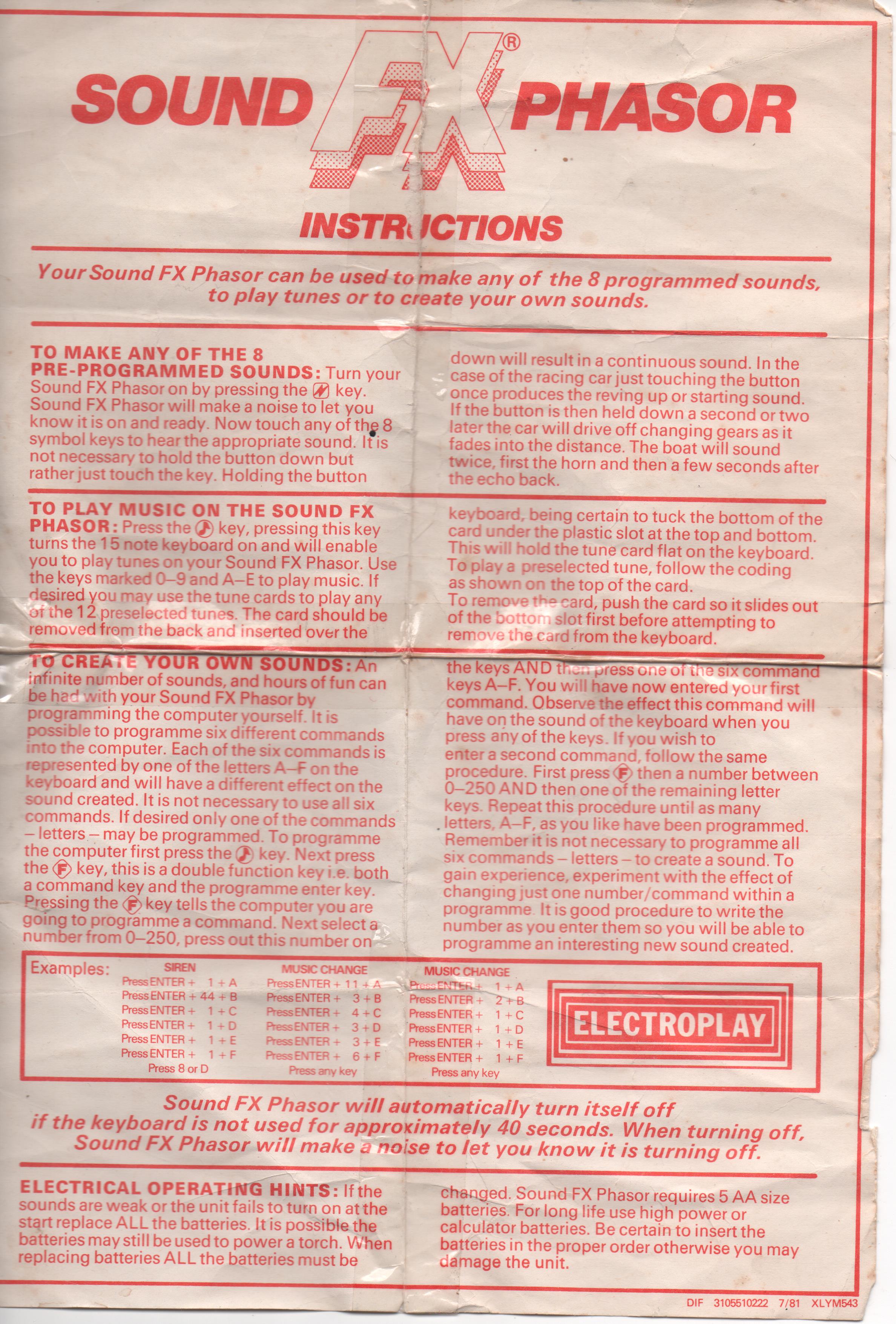
The original manual is a
complete disaster. The text reads
like botched together by a random clueless circuitbender - throwing in
buzzwords like "programming" and "computer", treating the user like an
idiot because it explains absolutely nothing about meanings of individual
parameters or inner working of the synth. This excerpt is really everything
it tells about.
| TO CREATE YOUR OWN SOUNDS: An infinite
number of sounds, and hours of fun can be had with your Sound FX Phasor
by programming the computer yourself. It is possible to programme six different
commands into the computer. Each of the six commands is represented by
one of the letters A-F on the keyboard and will have a different effect
on the sound created. It is not necessary to use all six commands. If desired
only one of the commands - letters - may be programmed. To programme the
computer first press the 'musical note' key. Next press the 'F' key, this
is a double function key i.e. both a command key and the programme enter
key. Pressing the 'F' key tells the computer you are going to programme
a command. Next select a number from 0-250, press out this number on the
keys AND then press one of the six command A-F. You will have now entered
your first command. Observe the effect this command will have on the sound
of the keyboard when you press any of the keys. If you wish to enter a
second command, follow the same procedure. First press 'F' then a number
between 0-250 AND then one of the remaining letter keys. Repeat this procedure
until as many letters, A-F, as you like have been programmed. Remember
it is not necessary to programme all six commands - letters - to create
a sound. To gain experience, experiment with the effect of changing just
one number/command within a programme. It is good procedure to write the
number as you enter them so you will be able to programme an interesting
new sound created.
Examples:
SIREN
Press ENTER + 1 + A
Press ENTER + 44 + B
Press ENTER + 1 + C
Press ENTER + 1 + D
Press ENTER + 1 + E
Press ENTER + 1 + F
Press 8 or D
|
MUSIC CHANGE
Press ENTER + 11 + A
Press ENTER + 3 + B
Press ENTER + 4 + C
Press ENTER + 3 + D
Press ENTER + 3 + E
Press ENTER + 6 + F
Press any key
|
MUSIC CHANGE
Press ENTER + 1 + A
Press ENTER + 2 + B
Press ENTER + 1 + C
Press ENTER + 1 + D
Press ENTER + 1 + E
Press ENTER + 1 + F
Press any key
|
In the 1st example here of course
also other notes can be played; the siren howl tempo follows note pitch.
Example 2 is a simple organ with strong fast vibrato (tempo follows note
pitch). Example 2 is a simple bright high organ with slightly purring overtone
(like the German telephone free-line signal). |
Press the 'musical note' button and play a note on any key beside 'F'.
The synth mode starts now with a primitive "guitar" preset sound (2-bit
wannabe sawtooth). Its (anyway too short) decay gets truncated by key release,
which seems to be the default behaviour in synth mode. Any synth parameter
is edited by pressing "enter" (F button), typing any number (this sounds
a blip) and pressing one of the 6 letter buttons. Each letter button (also
F) sets a corresponding parameter. It is hard to figure out what they exactly
do; depending on the parameter. While their range seems to be 0..255 (8
bit, typing bigger numbers wrap around, ignoring upper bits), typing more
digits sometimes seems to do more complex things (which may be buffer overflow
bugs). Parameters also interact with each others.
After switching on (note icon button), you need to first play a note
before setting a parameter, else glitches occur, those however can be used
to get different sounds. Apparently default values of the preset sound
are only initialized when playing a note before setting any parameter.
Particularly the octave of the main voice can strongly change, e.g. depending
on which effect noise was previously played. Possibly such semi-random
glitches made the designer give up any plans of describing synth parameters
in the manual.
This produces siren-like effects by a triangular pitch envelope. Parameter
A sets the vibrato speed by changing the pitch envelope steepnes (0=fastest,
255=slowest). B apparently sets the upper and lower ramp limit, i.e. changes
the bounds between that the triangular pitch envelope ramps up and down
with the rate selected by A, which makes the vibrato simultaneously deeper
and slower (0=shallowest, 255=biggest amplitude). At high depths the pitch
will wrap around and thus low note start at a high pitch ascending further
until wrap point and continue ascending from the lowest pitch to the max
and return to lowest vice versa. Regard that A defaults to off (no vibrato)
and thus must be set to make B take effect. But both must be set 0 to disable
pitch envelope again.
Pressing the note icon button always resets A and B (removes pitch
envelope). Then press 2x F (do not play a note) to keep parameters C..F
of the previous sound.
-
decay envelope + suboscillator (C)
This modifies the volume decay envelope. I haven't fully figured out
the details. Apparently the decay switching frequency for the analogue
decay circuit also acts as a suboscillator (e.g. bass) that may decay at
different rates (pulse density modulation). Parameter C seems to particularly
change the lowest level (like "sustain" in ADSR) to those the oscillator
decay during held notes. Values >15 make it decay fully, and higher values
decay faster. 0=no decay (plain continuous tone). 255=both decay fastest.
Values in between seem to make the suboscillator decay slower and/or less
low than the main oscillator and affect its pitch, which adds a buzzy zippernoise-like
additional tone. It may be that the step width and -position of the decay
get controlled this way.
Regard that while the default preset sound contains decay (C=255?),
the first manual change of any parameters disables decay (sets C=0?), thus
it needs to be set by hand if you don't want a continuous tone.
Normally the tone immediately stops by key release, although sometimes
(using parameters A, B?) a short delay occurs. I don't know if there is
a hidden parameter for this or just a glitch. (In opposite to this, the
8 preset sounds of effect mode can run a few seconds without holding a
key.)
-
square LFO suboscillator (D)
Parameter D sets a frequency ratio to modulate the main voice with
a 1:1 square LFO at 100% depth, i.e. it chops the tone on and off with
a selected fraction of the note pitch. (0=off, 1=fastest, 255=slowest).
Low ratios (high frequencies) fall into the hearing range and so act as
a suboscillator to produce a bass voice. E.g. 2 sounds an octave lower.
Higher ratios make a purring buzz (like missing the ball in "Pong",
or clangs from the Namco game "Bomb Bee") while even higher
ratios make the tone toot on and off with a tempo proportional to the note
pitch. Apparently this edits the waveform on a deeper level than a simple
LFO, because combined with E and F it can turn the tone much lower and
buzzier. So it may be that it inserts a blank piece into the waveform by
halting the oscillator instead of muting it during zero.
-
waveform suboscillator + volume envelope (E, F)
Parameter E and F do the same, thus the same sound is produced with
both values exchanged. So I conclude that internally they may be arguments
of an addition, multiplication or XOR to produce the resulting waveform
and envelope. Setting at least one of these 0 or 1 disables the suboscillator.
Regard that E defaults to off and thus must be set to something else to
enable this suboscillator.
Parameter E/F add an at least 1 octave lower suboscillator with selectable
waveforms that modulates the resulting tone with buzzy multipulse textures
approximating linear volume envelopes. The modulation depth is 50% (unlike
the the square LFO) and it has different timbres (0=off, 1=off, 2=on, 3..255=waveforms
or noise). With E and F set to the same value and other than 0 or 1, the
volume pulses high and low (square LFO similar like parameter D). Like
D, small numbers produce bass voice; a bigger number pulses slower. When
both values differ by 1, a kind of beat frequency modulates it with falling
pulse duration envelope. Bigger differences make it beat faster, which
may hint that the output is derived from a phasing process, which would
explain the name "Phasor". Depending on the values, the pulse duration
envelope can be falling sawtooth shape (difference 1), but gradually becomes
faster and then triangular to irregular if the difference between E and
F is set higher. Unlike parameter C, this envelope speed is proportional
to the note pitch. Tones with low E/F difference can sound like hemisync
bleeps of old mindmachines (of course here mono). Some high values can
produce LFO-like tekkno sound loops those add rhythmic crackling or switch
the suboscillator rhythmically on and off.
On oscilloscope the phasing/beating waveform has only 2 volume levels
(about 50% and 100%) made from 2 mixed long multipulses. In total the audio
is mixed through resistors from 4 digital pins, but the 3rd pin seems to
not affect beating and the 4th is pulse density modulated decay envelope
control, that also acts as a suboscillator. The logic analyzer reveals
that only pin 16 outputs a complex repeating multipulse of falling PWM
pulsewidth, that apparently intermodulates with plain squarewaves from
pin 17 and 13.
The values seem to have no logical order, thus likely rather technical
than ergonomical reasons. E.g. 2, 3, 4, 6, 8, 9, 12, 15, 18, 21, 24, 27,
30, 32 add harmonic overtones, while 5, 7, 10, 11, 13, 14, 16, 17, 19,
20, 22, 23, 25, 26, 28, 29, 31 produce disharmonic noises. I suspect that
the bits control an RNG algorithm like shiftregister feedback noise. Sometimes
the same value even seems to randomly produce different timbres, so the
internal state may produce varying bit loops when ratios are not prime
and the random seed differs. Generally many sounds resemble POKEY (the
famous Atari chip), but tend to be less disharmonic and have no detuned
bass problems, so the frequency resolution is likely higher. Apparently
it also fails to produce fully atonal hiss (except as part of effect noises).
So its relation to POKEY is more like that of Phase Distortion to FM; despite
similar principles, the character of the timbres and its parameters can
substancially differ and make of it a unique sound source.
Also Parameter D affects the timbre and makes it even buzzier. So strongly
detuned low notes can produce e.g. motor noises or tekkno drones. It may
be that this function similar like noise modulation in phase distortion
synths. Parameter B seems to also affect pitch of both suboscillators,
hence high values can turn the tone even lower and produce more extreme
noise when combined with waveforms of E/F.
Parameters D, E and F interact with each other in complex ways those
can produce long tone and noise loops. I suspect that bit patterns of different
lengths get XORed with each other or something similar, so they need to
be treated as a whole. The tempo of everything they do is always proportional
to the note pitch frequency. So the ascending pitch of the siren effect
by parameter A and B can result in an accelerating throbbing statccato
when pulsed by the LFO parameter D.
This seems to be an internal parameter that can not be set directly.
But you can change the base octave of the synth by playing an effect noise,
switching to synth mode and pressing 2x 'F', which leaves residues of the
previous sound in RAM including the octave setting. Hence entering parameters
C, D, E, F manually (A and B reset anyway) will now make them sound in
the octave of the previously played effect noise.
The "guitar" default preset is set automatically by playing a note
after power on. It resembles the parameters (A=0, B=0, C=255?? , D=2, E=0?
F=0?), but the tone is 1.5 octaves lower during attack, thus C and possibly
A and B seem wrong. After power-on, pressing 2x "F" (enter) instead of
a note prevents this and so keeps parts of the previous parameters in memory.
When the last sound was the APO bass, it adjusts the synth to a very low
short crackling buzz sound (A=0??, B=0??, C=255, D=255?, E=120?, F=255?).
I find no obvious identical settings, because changing one parameter apparently
resets others to "sane" values. This confusing behaviour was likely done
to need less typing for popular synth patches.
The effect noises seem more complex than what can be manually done
with synth parameters. Although I haven't fully researched details, I suspect
that those "Living Sounds" contain additional preprogrammed fast envelope
sequences. They are not supposed to be editable nor played on note keys,
but when previously an effect noise was played, switching to synth mode
and pressing 2x "F" keeps residues of it in memory. But only the "police
car" timbre stays fully intact as an organ tone. The "boat" turns into
a low organ tone, which lowest playable note is somewhat higher than that
ship horn. Of the "ufo" part 1 and 2 (release button to stop) produce a
fast purring noisy tone, but part 3 a surprising disharmonic semimetallic
buzzing clang. From the "train" remains only a high organ beep (so its
rough hiss noise is likely out of reach); "telephone" becomes the same.
The "bee" turns into a buzzy kind of e-bass; stopping later makes it duller.
Also "racing car" turns into a buzzy decaying bass. The "helicopter" becomes
a (heavy metal chord?) noisy and buzzy low synth bass; if stopped later,
the result is less buzzy with decay. The results can be a little random,
likely depending on the exact time when the Living Sound gets stopped.
But they can not be stopped at their begin at arbitrary spots (not even
with "on" buttons) which hints that they occupy full CPU capacity with
nothing left for sensing other buttons. The stop behaviour varies with
the noise; e.g. "train" and "boat" need 1 second to recognize stop, while
others stop faster.
note: Some of my conclusions may be completely wrong, and there
may be hidden features in a way that certain entered numbers or individual
bits in them may e.g. select FM operators or other modulation targets
or set things from an internal list in unobvious ways. It feels like pushing
random buttons on a DX-7 without display to figure out by ear how
it works. This thing does program loop synthesis, i.e. it is a "dirty"
softsynth that messes with internal parameters in all kinds of strange
ways to generate a variety of different sounds from very little memory.
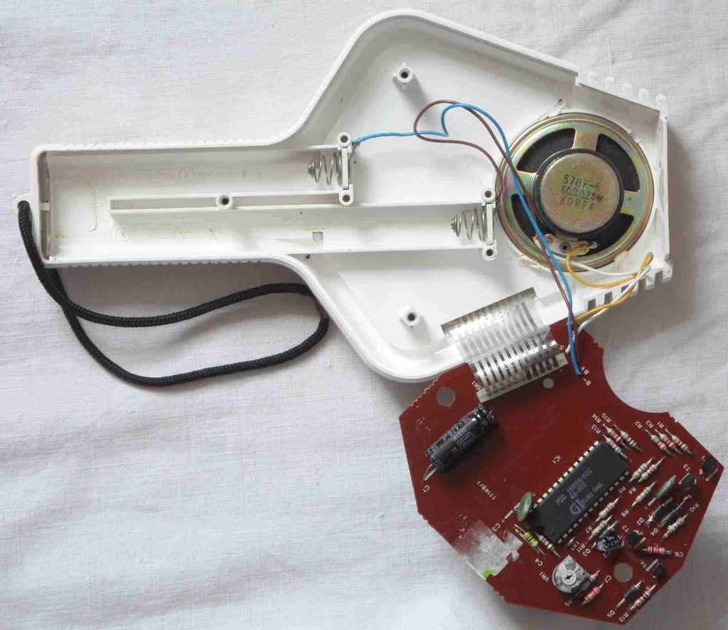
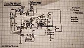
circuit bending details
The Sound FX Phasor is built around the microcontroller "PIC 1655A-522"
running a software synthesizer. It has a tuning trimmer for pitch adjustment.
caution: The touchpad hangs on a short
and flimsy foil cable, very similar like those in early Sinclair
homecomputers. Although it is less delicate than the infamous Casio
LCD foil cables, it may tear easily when removing the PCB. If necessary,
the cable can be carefully pulled out of its PCB connector and later pushed
back in, however repeated removal may scratch the conductive paint, and
any sharp fold may crack it, thus better leave it in place.
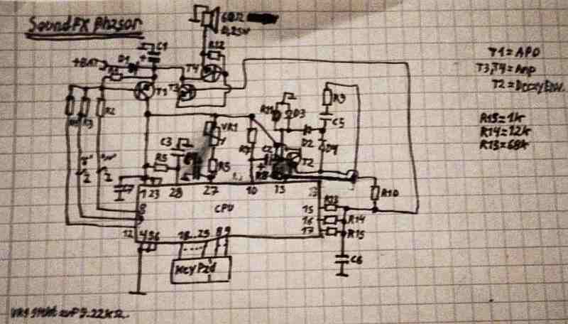
The 60 Ohm 0.25W speaker is wired to a single-endet darlington amp made
of transistors T3 and T4. The APO circuit switches positive voltage to
the CPU through T1.
In synth mode, waveform pin 13 (suboscillator and decay rate control)
and 17 (main oscillator) output plain squarewaves, while only pin 16 outputs
complex generated multipulse patterns depending on the synth parameters.
(Unlike my expectation, the multipulse is not on another pin when swapping
values of parameter E and F.) Rise on pin 10 starts the decay envelope.
The pitch of the "guitar" default preset starts 1.5 octaves lower during
attack. In noise effect mode also pin 13 and 17 can contain multipulses.
Pin 15 only outputs waveforms in sound signals and "telephone". Likely
the mixing at the base of power amp transistor T3 does some kind of analogue
multiplication (distortion) that results in more complex phasing waveforms.
Pin 17 seems related to parameter D, and by its high amplitude (lowest
resistor) sort of chops the rest.
keyboard matrix
There are no eastereggs. The effect noise buttons are wired parallel to
cipher buttons '0' to '7'. The 2 power buttons for effect and synth mode
have own CPU pins outside the matrix.
|
22
|
23
|
25
|
24
|
|
CPU pin
|
|
in 1
|
in 2
|
in 3
|
in 4
|
in / out
|
|
o
G1
'0'
helicopter
|
o
A1
'1'
telephone
|
o
B1
'2'
racing car
|
o
C2
'3'
ufo
|
out 1
|
19
|
o
D2
'4'
train
|
o
E2
'5'
bee
|
o
F2
'6'
boat
|
o
G2
'7'
police car
|
out 2
|
18
|
o
A2
'8'
|
o
B2
'9'
|
o
C2
'A'
|
o
D3
'B'
|
out 3
|
20
|
o
E3
'C'
|
o
F3
'D'
|
'o'
G3
'E'
|
enter
'F'
|
out 4
|
21
|
The input lines are active-low, i.e. react on GND. Any functions can
be triggered by a non- locking switch in series to a diode from one "in"
to one "out" pin.
eastereggs:
APO deletes the synth patch in RAM after 46 seconds of idle. To disable
it, simply wire CPU pin 7 to ground 0V. Because the hardware consumes about
32mA when on (1uA during standby), install a power switch. There are multiple
options for this beside the obvious one. To preserve the original warning
bass note, you may place your switch into your line to pin 7 to reenable
APO. Instead of a hardware switch, you might also install a non-locking
button switch to pull down reset pin 28 to immediately drop into standby
(no bass note, has no benefit). Add an optional power LED (e.g. at CPU
pin 1 through 10k resistor to ground 0V) as a reminder to turn it off to
conserve battery.
Pulling pin 6 hi (normally wired to GND) disables the keyboard matrix
outs and so disables all keys except power buttons.
Clock rate is controlled by an RC oscillator at CPU pin 27 (capacitor
to GND, resistor to positive supply voltage of the CPU). You may replace
the 22k trimmer VR1 with an external pot or other pitchbend control. (It
is not DC controlled, thus sensitive to RFI.)
The analogue envelope circuit (parameter C) uses transistor T2 and
electrolytic capacitor C2. Decay speed is controlled by a PWM signal (that
also acts as suboscillator) from CPU pin 13 and start is triggered by rising
edge of CPU pin 10. Capacitor C2 (4.7uF) controls decay duration.
Pulling pin 10 lo (through a resistor to avoid CPU damage) causes slow
attack in all sounds. (This is independent from the simulated PWM volume
envelope of parameters E/F.)
pinout PIC 1655A-522
The "General Instruments PIC 1655A-522" (28 pin DIL, "522"=software number
of internal ROM) is the CPU of the Sound FX Phasor. Technically
it is the 8-bit microcontroller PIC 1655A, which has 32 byte RAM and 512
word of 12-bit mask ROM containing a monophonic software synthesizer, featuring
8 preset effect noises and a user programmable synthesizer with 6 parameters
(each 8-bit?). Because the chip supports no analogue ports, the audio signal
is mixed from 4 digital pins through resistors. One of them is pulse width
modulated decay envelope speed (that also acts as suboscillator) connected
to an external transistor circuit with capacitor for the decay envelope.
The "1983 PIC Series Microscomputer Data Manual" shows on page
175 the PIC1655A example application "7.3 Sound Generation Using a PIC
Microcomputer" with source code and schematics for a similar toy with 8
effect noises, which however contains 2 melodies instead of the synthesizer,
sounds are simpler and pin assignment differs. It apparently refers multipulses
as "pulse trains". Most interesting is that one of its sounds is indeed
refered as "Phasor"! (gun in space war games).
| pin |
name |
purpose |
| 1 |
/RTCC |
real time clock counter (wired to 2 | not used) |
| 2 |
VDD |
supply voltage +5V |
| 3 |
VXX |
out pins supply voltage in (wired to 2) |
| 4 |
VSS |
ground 0V |
| 5 |
TEST |
test mode (wired to 4) |
| 6 |
RA0 |
key matrix out disable in (wired to 4) |
| 7 |
RA1 |
/APO disable in (not used) |
| 8 |
RA2 |
/effect mode power on in |
| 9 |
RA3 |
/synth mode power on in |
| 10 |
RB0 |
decay envelope trigger out (rising edge) |
| 11 |
RB1 |
(not used | lo out) |
| 12 |
RB2 |
APO out (hi when on) |
| 13 |
RB3 |
decay envelope PWM + waveform out (synth square) |
| 14 |
RB4 |
(not used | hi during "train" noise) |
| 15 |
RB5 |
waveform out (signals, "telephone") |
| 16 |
RB6 |
waveform out (synth multipulse) |
| 17 |
RB7 |
waveform out (synth square) |
| 18 |
RC0 |
key matrix out |
| 19 |
RC1 |
key matrix out |
| 20 |
RC2 |
key matrix out |
| 21 |
RC3 |
key matrix out |
| 22 |
RC4 |
key matrix in |
| 23 |
RC5 |
key matrix in |
| 24 |
RC6 |
key matrix in |
| 25 |
RC7 |
key matrix in |
| 26 |
CLKOUT |
clock out (not used) |
| 27 |
OSC |
clock oscillator (capacitor to 0V, resistor to VDD) |
| 28 |
/MCLR |
/reset |
The PIC1655A is the mask rom version of the eprom based PIC16C55. Both
are very close relatives of each other and hence even have a similar rom
dump mode, despite it is activated differently. With the documented PIC16C55
pin 1 needs to be set hi and pin 28 connected to programming voltage to
make it output rom data bits at pins RB7 (msb) to RA0 (lsb) in a loop (controlled
by clock rate, no address signals). The undocumented PIC1655A instead needs
the TEST pin 5 pulled to 3V to start dumping, which after reset starts
at address $1FF (reset vector) wrapping around from $000. So with some
help I managed to dump the "Sound FX Phasor" rom. I had to desolder pins
6, 7, 15, 16, 17 and circumvent APO (pull base of T1 through 1k resistor
to +BAT (behind diode)) to prevent powering off when 12 goes lo. I also
wired a 100nF cap parallel to C6 to reduce clock speed (CLKOUT about 370Hz)
to record the data (pins 6..17 = bits 0..11 | data sample rate set to 500kHz)
without capacitive distortion. As expected, the 12-bit word repeats every
512 steps of CLKOUT. I also could examine some audio pin signals. (I had
to remove the 100nF cap to run properly, which now needed 4MHz data sample
rate to see CLKOUT properly.)
Likely also any PIC16C55 programmer can be easily rewired to read a
PIC1655A (beware of its programming voltage, that may be deadly to the
mask rom version) by feeding 3V to TEST pin 5. That pin seems to accept
voltages at about 1.4 to 3.7V to output rom data. Below 1.4 it gets distorted,
while above 3.7 came garbage (may do something else, like dumping current
RAM content for debug). Unlike newer PIC the 1655A is fortunately unprotected.
SeanRiddle mentioned that the PIC1650A instead needs 5V at TEST and RA3
pulled lo to dump rom.
Because this PIC supports no interrupts, the whole program is one big
loop. The chip is Havard architecture (separate code and data path) with
fixed size 12-bit instructions (containing an operand) and fixed execution
time, which makes it very crash resistant and effective for simple waveform
programming. By shitshot behaviour I would not have guessed it to be a
softsynth. But Havard likely also implies that it can not accidentally
output its ROM code as waveforms. Likely the code can be easily adapted
to a newer flash based variant like PIC16F57. So theoretically it may even
be possible to install it with a bugfixed/more ergonomic upgrade of the
code inside the original instrument.
The unused pin 7 disables the annoying APO so long it is pulled lo.
Pin 17 goes hi only during the "train" effect noise and nowhere else (may
be dead code from older software, or planned to switch a filter or light
effect for a different toy). Pin 6 (wired to GND) disables the keymatrix
out pins when pulled hi (i.e. no keys except the 2 power-on buttons work).
Powering on with both pin 8 and 9 pulled lo starts in noise effect mode.
Also pulling APO resistor from pin 12 hi (turns supply voltage on) during
standby starts noise effect mode (hence can not be used to continue from
standby with intact synth patch in RAM). Pin 11 stays always pulled low.
Strange is that pin 1is wired hi trough a separate wire bridge (not PCB
trace) despite pulling it lo has no effect; likely a prototype version
used the eprom version PIC16C55 which uses this pin for eprom write mode.
Pin 10 rising edge (pull low and release) retriggers the analogue decay
envelope. Holding pin 10 lo (through a resistor to avoid CPU damage) causes
slow attack in all sounds.
Tones from pin 13, 15, 16, 17 are mixed through resistors to form the
tone waveform. (pin13=R10 5.6k, pin 15=R13 68k, pin 16=R14 12k, pin 17=R15
1k). But pin 15 is only used during few sounds (button blips, power-on
beeps, APO warning bass, effect noise "telephone"), so only 3 bits remain
for the synth waveform, mixed from in synth mode 2 squarewaves and a complex
multipulse. The result is routed through the analogue decay circuit. The
pulse width(?) from pin 13 controls the analogue decay rate (synth parameter
C); the frequency is a fraction of the note pitch and additionally acts
as a (often bass) suboscillator. |
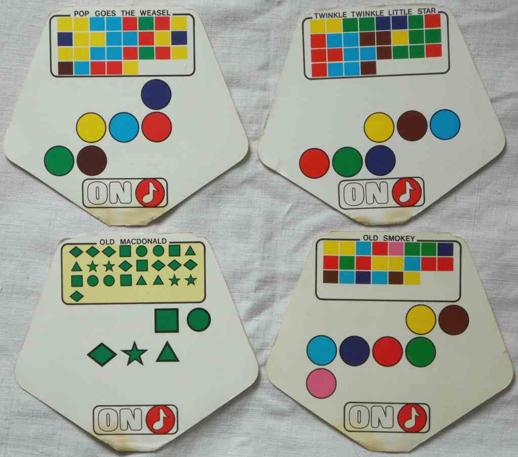
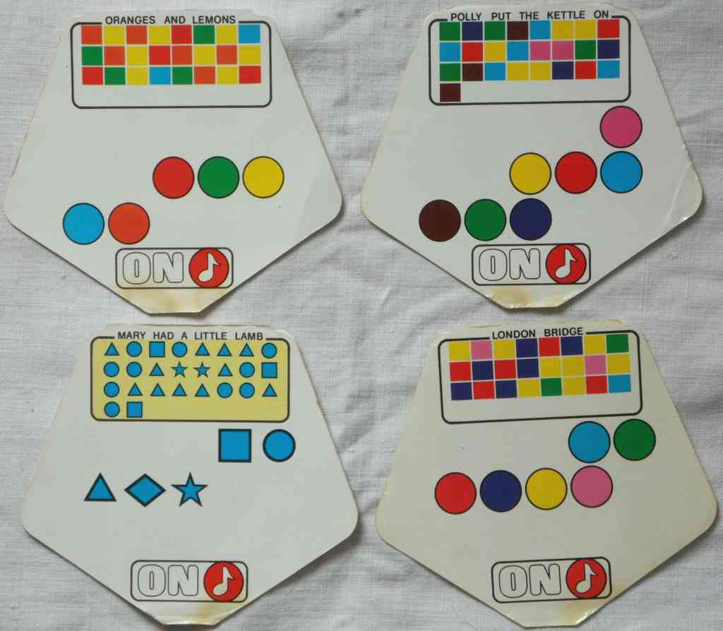
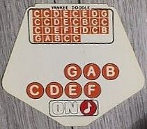
The instrument has no built-in demo melodies (so it keeps its tiny rom
for more interesting stuff), but in its bottom a compartment for originally
6 musical score card overlays. They contain each 2 short songs to be manually
played on the touchpad by pressing coloured circles and other symbols on
its keys.
 |
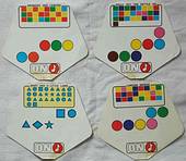 |
 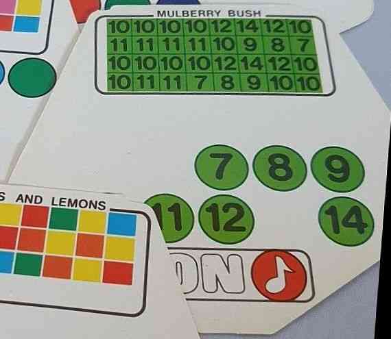
 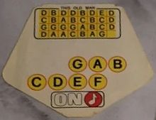
(web photos of missing cards) |
With my specimen 2 are missing (song names seen on internet photos).
-
London Bridge | Old Smokey
-
Twinkle Twinkle Little Star | Polly Put the Kettle On
-
Pop Goes the Weasel | Oranges and Lemons
-
Old MacDonald | Mary Had a Little Lamb
-
Yankee Doodle | This Old Man ? [missing]
-
Mulberry Bush | When The Saints ? [missing]
It is unknown if other cards with synthesizer patches and parameter reference
exist; IMO these would make much more sense, but the manual mentions none.
questions: Did they sell separate
overlays e.g. with synth sounds? Was the case designed for something else
(e.g. a handheld computer barcode scanner)? Were any other kids toys released
with the brand name "Electroplay", or was this just a label by another
company?
The Sound FX Phasor seems quite rare. Likely it did not sell
well because of too many quirks and unobvious operation. If Kraftwerk would
have got his hands on it, everybody for sure would name it in the same
sentence with Speak & Spell. Another awesome complex sound toy
was Tyco - HotKeys.
| removal
of these screws voids warranty... |
|
|
 |

|
|
| |
back
|
|