|
These are the keyboards with Casio's bipolar multipulse squarewave sound engine. With their linear volume envelopes, the sound style is Casio's closest equivalent to MC-3, although timbre and percussion quality is one notch higher. Unfortunately the envelopes end too soon, and there is no fingered chord mode in any of these keyboards.
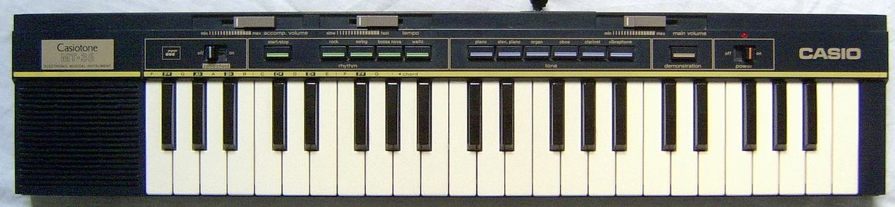
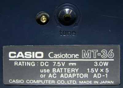
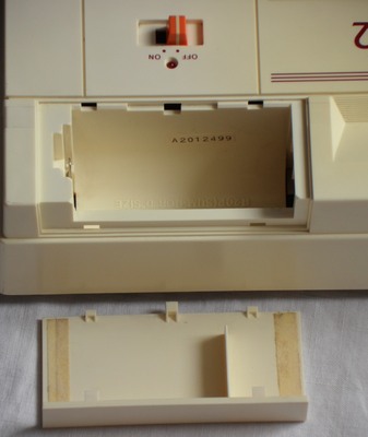
Unusual is that the case plastic is not black but a very dark blue. A white version of this instrument was released as Casio MT-35 and Realistic Concertmate 400. The original German retail price of the Casio MT-35 in a German Casio prospect of 1985 and Conrad catalogue of 1986 was 299DM (about 150€).
| base | = dull semi-analogue drum |
| snare | = dull shift register feedback noise |
| open & closed hihat | = unique electronic metallic timbre |
 |
 |
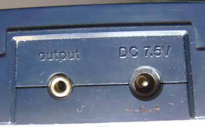 |
polarity protection diode added, power supply jack polarity corrected.
The percussion of the rhythm features an unusual metallic clicking hihat (made from semi-metallic shift register feedback noise) that strongly resembles Casio SK-1. The dull base drum sounds unspectacular. Also the snare is a bit dull but has a nicely grainy POKEY timbre (mixing both shift register noises). But these are no typical blip percussion, because their decay envelopes are shaped by a capacitor that prevents zipper noise. Unusual is that despite partly digital percussion, this instrument still has a real analogue tempo slider (can be set from very low to quite high). The combination of squarewave sounds with polyphony and digital percussion is quite unusual for Casio, because they normally used "Consonant-Vowel Synthesis" (2 mixed squarewaves with independent envelopes) in their older polyphonic instruments (see Casio CT-410V for explanation) and sample based timbres in later ones. So this sound engine was likely designed as a cheaper alternative to integrate main voice, accompaniment and percussion into a single sound IC.
Despite there is a single finger chord accompaniment, this instrument
has no manual chord mode; when the "casio chord" slide switch is on, the
thing always starts rhythm when any chord section keys are hit. The rhythm
always automatically inserts a fill-in (with accompaniment track when on)
every 4th bar; this stupid feature also existed in some Yamaha keyboards
(e.g. PS-30 and
MP-1),
but unlike there it can not even be turned off.
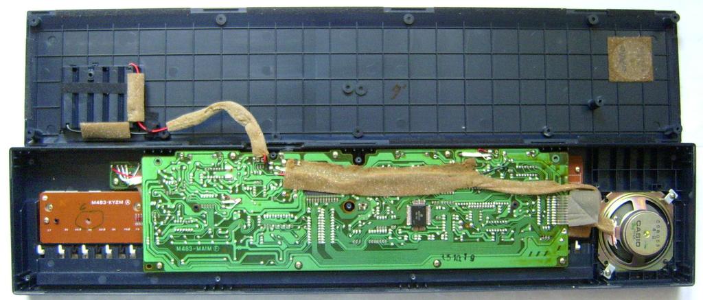
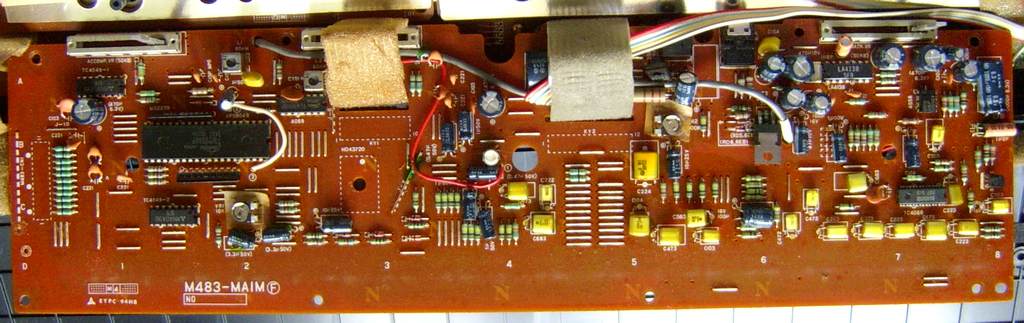
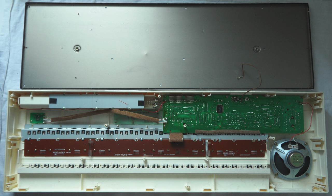
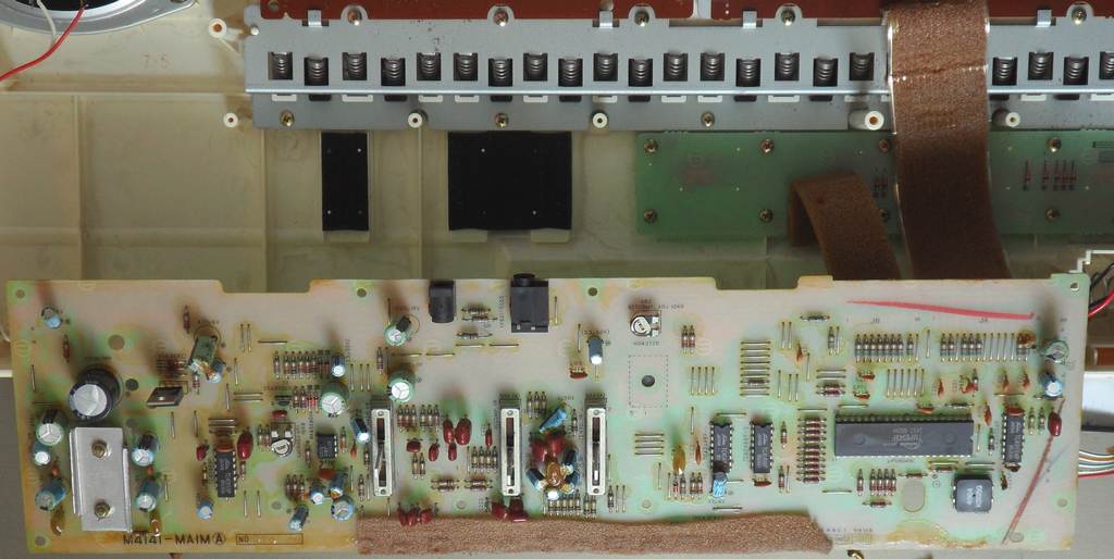
circuit bending detailsThe Casio MT-36 is based on the CPU "Toshiba TMP8049P, 3437" (clocked @ 4.96 MHz) with sound IC "Hitachi HD43720" and semi-analogue percussion.
keyboard matrixThis keyboard matrix was examined by me, based on the service manual of Casio CT-102. The matrix outputs from the CPU are routed through inverters (2x "TC4049BP").
The input lines are active-low, i.e. react on GND. Any functions can be triggered by a non- locking switch in series to a diode from one "in" to one "out" pin. The matrix inputs of CPU pins 12..16 are multiplexed with the sound
IC data bus and thus may make strange sounds when fed with wrong signal
timing.
Unlike my expectation I did neither find a manual chord mode nor sustain.
Apparently the MT-36 software was rewritten from scratch and not based
on MT-200 or CT-102.
|
According to the manual, the demo of MT-36 is the German folk song "Unterlanders Heimweh", but the melody is very different from the wonderful song of that name on ROM-Pack RO-551 (which corresponds to the famous demo of Casio VL-1 and was likely misnamed - read more about this unofficial Casio anthem here). I identified the MT-36 song as "Drunten im Unterland" (means "Down in the Lowlands", ©1835 by Gottfried Weigle, seen on YouTube with German lyrics) aka "Unterländers Heimweh" (regard the 'ä'). The MT-36 melody sounds like a rural folk waltz and resembles a bit "Little Brown Jug". The simple folk waltz tune is only a very short monoto that cycles through all 6 preset sounds again and again without any complex accompaniment changes or the like, but at least you can play to it or change the preset sound and tempo.
A competitive product to the MT-36 was likely Yamaha PSS-150, which looks and sounds quite similar.
 |
 |
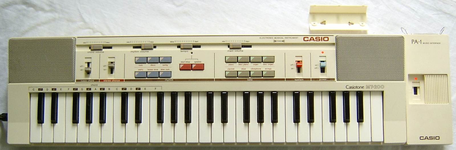
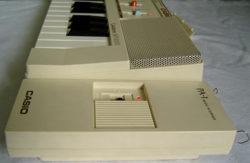
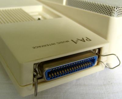
| The most unique feature is the slot for the optional parallel port interface Casio PA-1, with that it could be connected to a computer. | 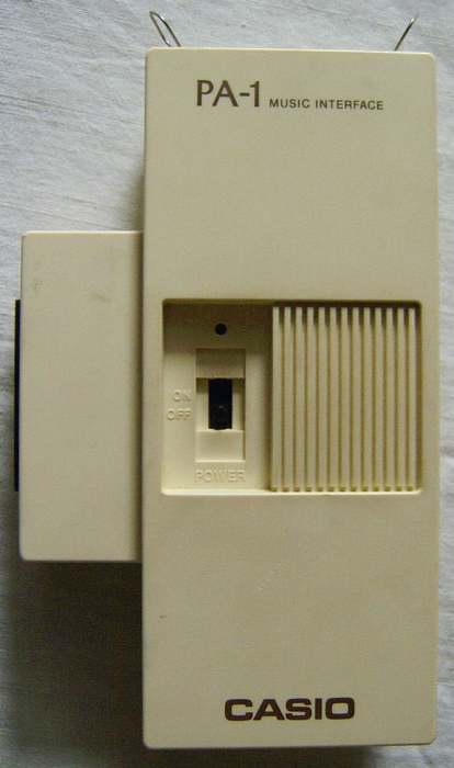 |
Also a black version was made (seen on eBay).
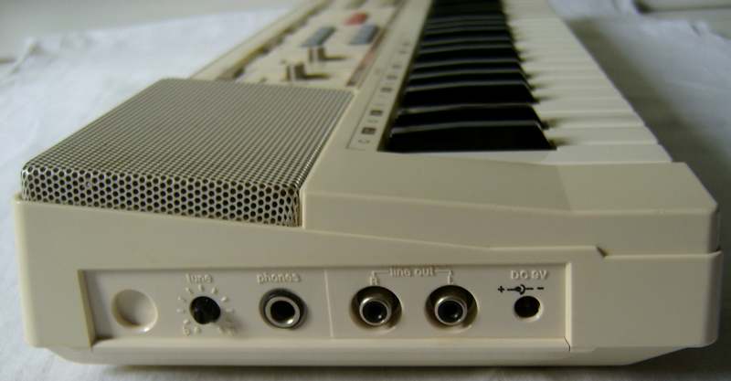
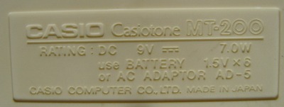
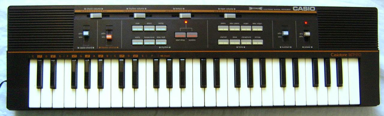
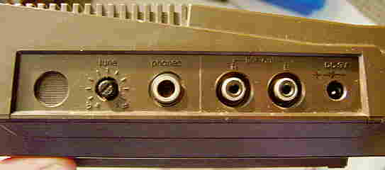
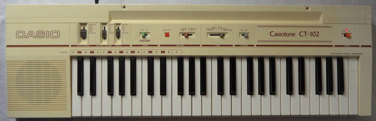
49 midsize keys 2 built-in speakers (mono sound generator routed through a stereo chorus) polyphony 8 notes (only 4 with chord or accompaniment) 8 preset sounds {piano, elec. piano, organ, elec. organ, clarinet, oboe, vibraphone, strings} 6 preset rhythms {rock, disco, swing, waltz, bossa nova, slow rock} no (automatic) fill-in separate chord & rhythm volume sliders sustain switch stereo chorus with on/off switch single finger chord (has manual organ chord with rhythm off) "bossa nova" rhythm has additional analogue conga drum complex multi-chip hardware: CPU= "NEC D8049C 557, 8349HX" (40 pin DIL , Intel MCS-48 with 2KB ROM) sound IC= "HD43720, 3J 48" (54 pin SMD) stereo chorus: BBD= "MN3206" (8 pin DIL, 128 steps), clock= "MN3102" (8 pin DIL) tuning knob slot for computer interface Casio PA-1 jacks for power supply, headphones & line out
 |
 |
 |
 |
 |
 |
 |
2 additional rhythms addable. auto-fill-in switch addable.
polarity protection diode added, power supply jack polarity corrected.
The main voice waveforms are bipolar multipulses and sound fairly ok. (IMO many Casio VL-1 waveforms sound more natural.) Worse is that the linear decay envelopes are too short. So even held 'piano' notes end already after 1s. Held notes of all other decaying preset sounds only last 0.5s. The sustain switch adds 0.5s sustain after key release (else notes stop immediately), but do not prologue held notes of decaying sounds. The 'vibraphone' has sustain always on and ignores that switch. Trilled keys produce a nice phasing and volume increase effect by occupying multiple polyphony channels. Interesting for playing is that the OBS preset sound buttons can also be pressed while keys are held down without stopping their notes. Like in MC-3, by rhythmically pressing them, many arpeggiator- like timbre changes can be created, thus this button field can be considered a realtime sound control, and unlike in many other digital instruments, the button field responds almost immediately without delay (which however causes some pop noises).
The stereo chorus adds a 6Hz chorus vibrato to the main and chord voice when enabled. But even when switched off, it still slowly pans the sound left and right with about 0.5Hz. Unlike my first expectation, there is no fingered chord mode in this instrument. But at least there is a manual organ chord mode with rhythm off (made from multipulse chord + dull bass voice with a little sustain).
Unlike MT-36 the "bossa nova" rhythm employs an additional analogue conga drum instead of the snare, and the base drum knocks louder (possibly by better speakers). The percussion also sounds a bit duller, which makes the grainy digital hihats less spectacular. Also the automatic fill-in of the MT-36 is missing, which makes the accompaniment patterns simpler but more versatile.
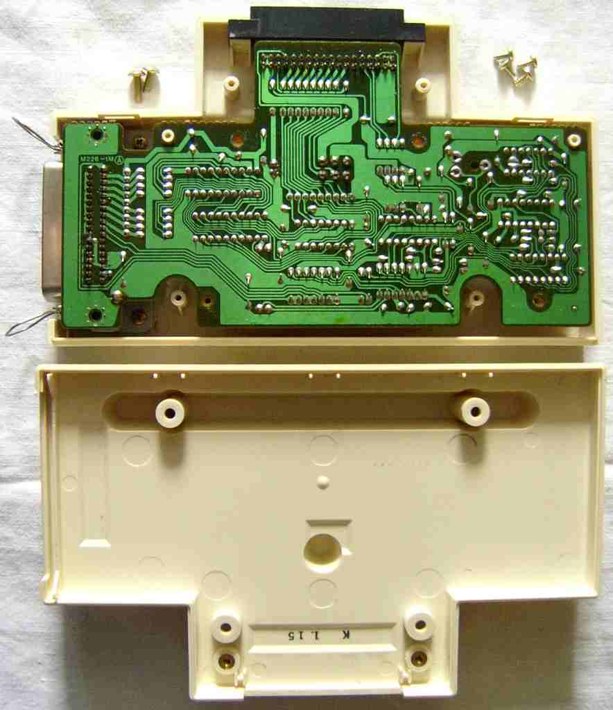
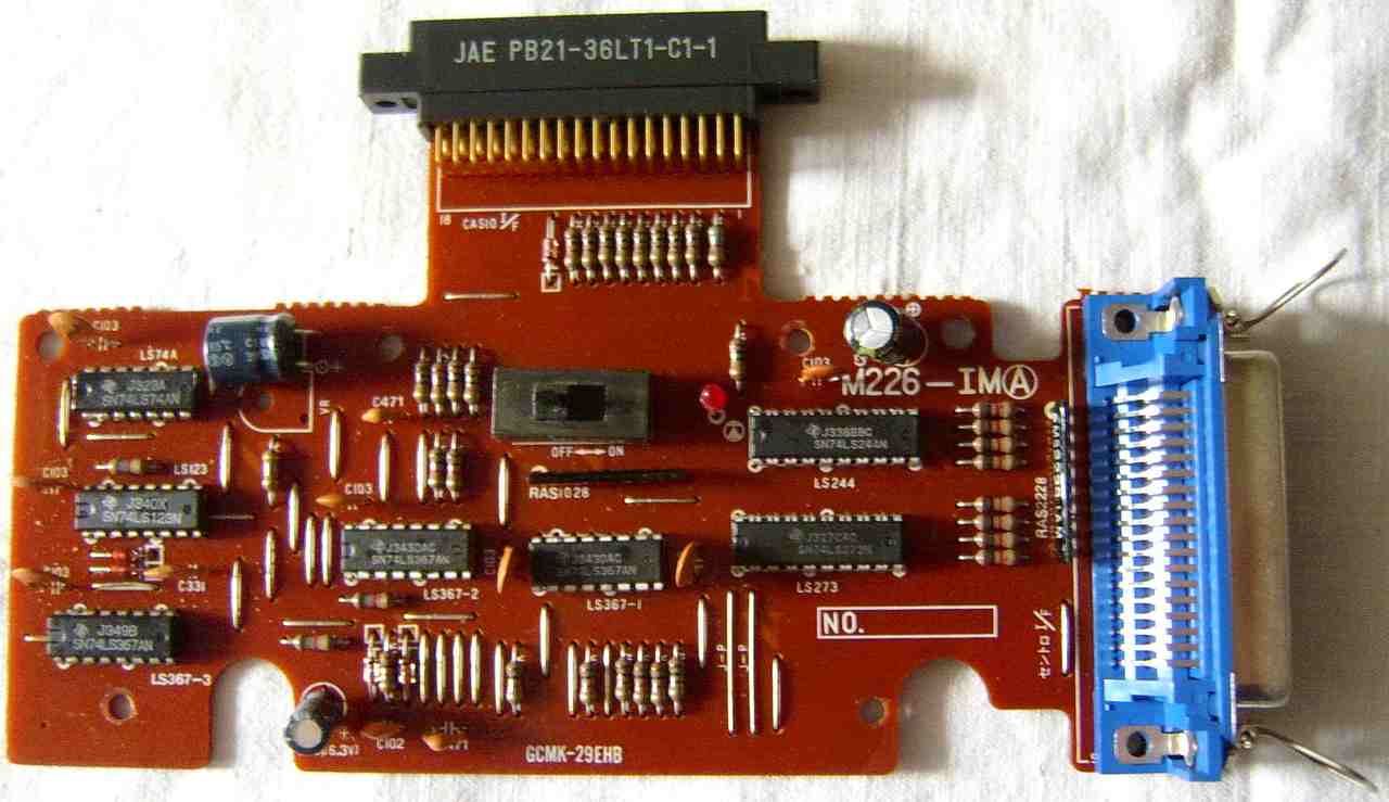
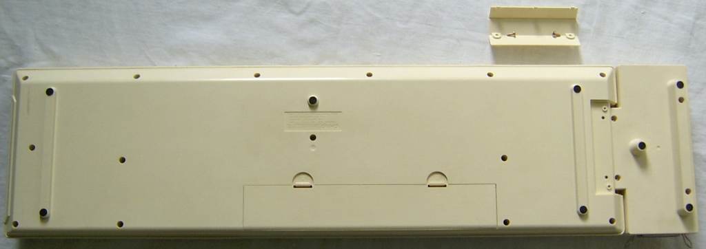
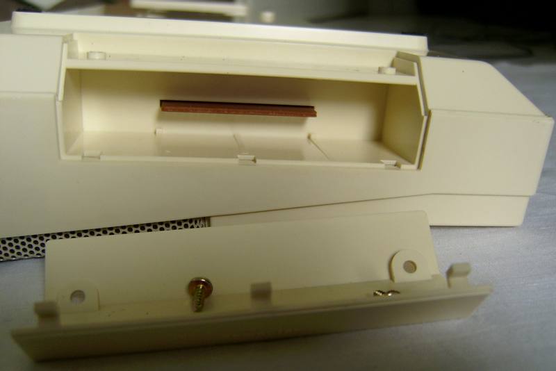
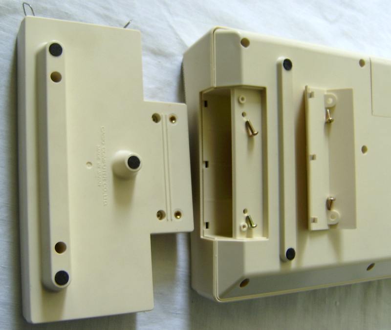
To the right it has a screwed lid where the parallel port interface PA-1 can be inserted and even screwed on at the case holes. This ultra-rare interface has a Centronics printer plug at its side and was intended as a MIDI predecessor. I never heard of any other Casio instrument supporting it. There is a switch on the interface that (as far I remember) stops rhythm when turned on without a computer. According to MT-200 service manual, the PA-1 supports data transfer only one way to play music programmed on a "personal computer". I.e. it was only like midi-in and can not be used as a master keyboard for e.g. entering music into sequencer software. This is a bit disappointing, seeing that the (otherwise not cheaply built) MT-200 of all used one of the weakest polyphonic Casio sound ICs. If Casio would have used a programmable synth chip like in MT-65, in 1984 this could have been a game changer. AFAIK the only computer that used the MT-200 to play music was the fairly big and expensive Casio FP-1100.
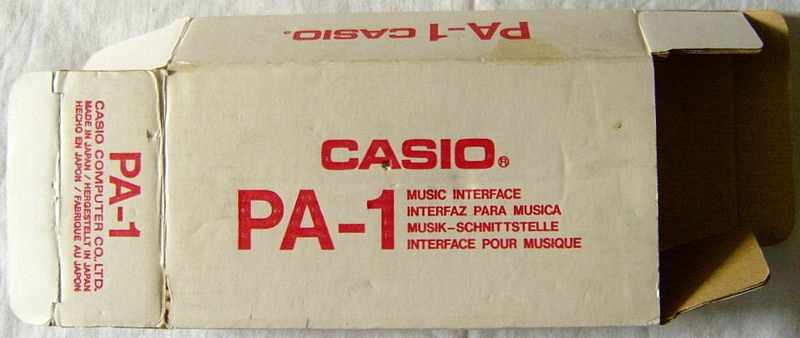
question: Does anybody know more
about the Casio PA-1 interface? Which other computers could use
it? Has anybody still software for it? The only other thing with "PA-"
in its name was the later released toy keyboard
Casio
PA-31, which had nothing to do with it. Casio also first released
the TA-1 tape storage
interface and later a TA-10
toy keyboard - did they do this with all their interface names??
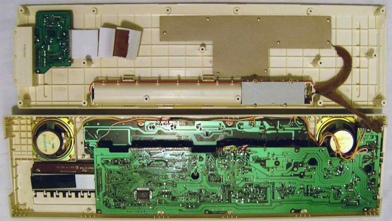
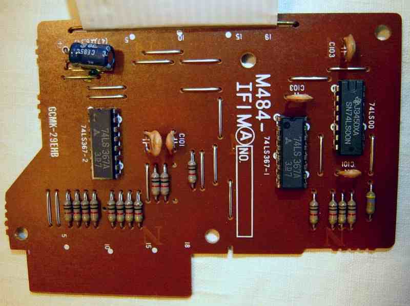
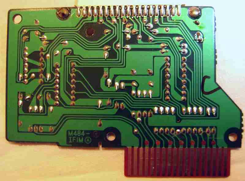
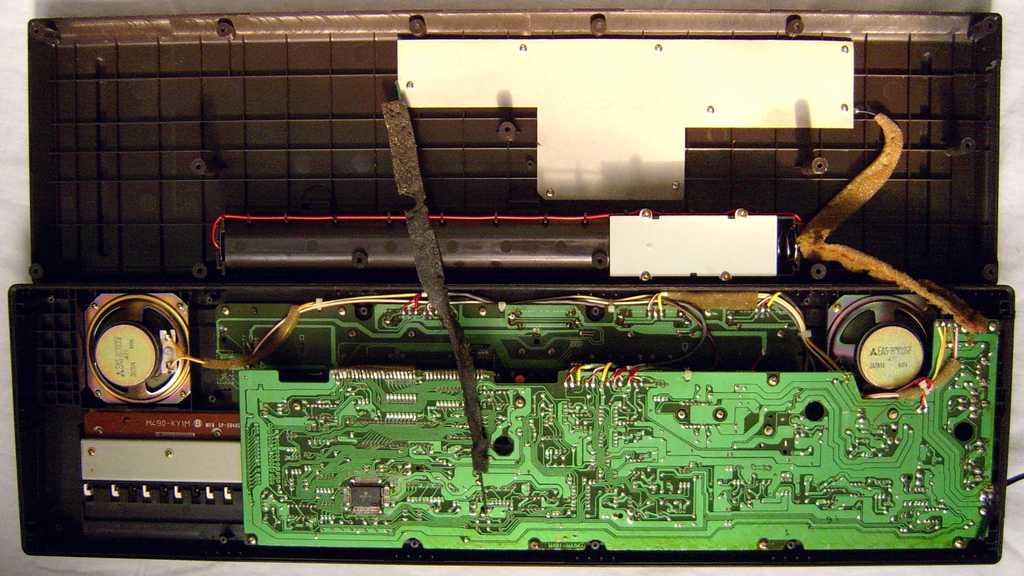
circuit bending detailsThe Casio MT-200 is based on the CPU "NEC D8049C 557" (clocked @ 4.96 MHz) with sound IC "Hitachi HD43720" and semi-analogue percussion. Casio MT-90 is the same, but lacks the computer port and a few related discrete components, despite the PCB still has empty solder holes and traces for it.
That is to say, there is a large analogue stereo chorus section based on BBD ICs. Even in "off" position it is not off but only switched to a slower and weaker mode. In MT-200 and CT-102 the unused CPU pin 38 pulls lo during preset sounds {vibraphone, elec. organ, strings} and was likely originally intended as an automatic control for this (or a vibrato circuit). Despite MT-200 has only a manual slide switch for its stereo chorus, a yellow cable from there goes to one side of an unsoldered wire bridge that was apparently originally planned by Casio to enable it (or switch it to fast mode) only during these 3 sounds. The given slide switch was instead likely planned for automatic fill-in, which exists as an easteregg. The percussion in 'bossa nova' rhythm triggers an additional analogue conga through CPU pin 23. computer portAccording to MT-200 service manual, the PA-1 is a Centronics interface with data transfer only one way to play music programmed on a "personal computer". I.e. it was only like midi-in and could not be used as a master keyboard for e.g. entering music into a sequencer software. Disappointing is that the MT-200 of all had one of the weakest polyphonic Casio sound ICs. Casio should have used a versatile programmable synth IC like D931C to make this into an exciting product.
In the service manual is a description of the parallel port protocol with timing chart. (/STROBE lo pulse needs to be 0.5..1uS. /RD lo pulse needs to be >300ms. /ACKNLG lo pulse needs to be >7us.) The ROM contents of the MT-200 CPU strongly differs from MT-36, not least because it had to support the computer interface, so it may be that there was not enough rom space left to include the demo. keyboard matrixThis keyboard matrix was originally examined by me, based on the service manual of Casio CT-102, and later corrected by that of MT-200 (which has different software). Unlike other models of this hardware families, the matrix outputs here are not inverted, but instead the matrix inputs to the CPU are switched through 2 tristate drivers TC40H367P and apparently multiplexed with computer port data. The matrix inputs of CPU pins 12..16 are also multiplexed with the sound IC data bus and thus may make strange sounds when fed with wrong signal timing.
The input lines are active-low, i.e. react on GND. Any functions can
be triggered by a non- locking switch in series to a diode from one "in"
to one "out" pin.
The rhythm naming in MT-200 service manuals is wrong (column KI8 = {Rock,
Swing, Bossa Nova, Waltz, Bossa Nova, Slow Rock, "", "", Comp} ) and its
buttons only have numbers in the wiring plan, so possibly software wasn't
finished when schematics was made. Unlike my expectation I did neither
find a fingered chord mode nor unused vibrato output (measured CPU pins).
The matrix place KI8->KC9 labelled "Comp" stops rhythm and has likely to
do with the PA-1 computer interface.
|
The German retail price in a Casio prospect of 1985 was 449DM.
 |
 |
 |
 |
polarity protection diode added, power supply jack polarity corrected.
The CT-102 was also released in black. The German retail price in a Casio prospect of 1985 was 499DM.
 |
 |
 |
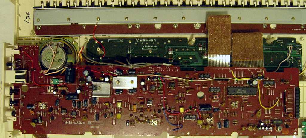
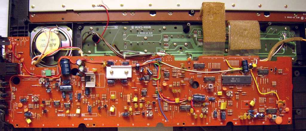
circuit bending detailsThe Casio CT-102 is based on the CPU "Toshiba TMP8049P, 3497" (crystal clocked @ 4.96 MHz) with sound IC "Hitachi HD43720" and semi-analogue percussion. It is closely related to Casio MT-36 and MT-200 (those have different software numbers); also here the CPU is an Intel MCS-48 variant with 2KB ROM (I dumped it).
sound generatorThis sound hardware was apparently Casio's first cheap polyphonic sound ic with integrated DAC, chord and percussion generator. The main voice generator is obviously a polyphonic successor of the great multipulse squarewave sound engine of Casio VL-1, but unlike there, the blocky waveforms are bipolar, i.e. made from 3 levels {-1, 0, +1} (which IMO did not improve timbre quality). So the sound IC has 2 DAC outputs for a main and a sub waveform, those are mixed through resistors in a ratio of 1:64. With held monophonic notes the main waveform looks like a normal multipulse, while the sub waveform has 3 levels {-1, 0, +1} and looks like the tone. During falling volume envelope, the equidistant "0" sections of the main waveform rapidly move many times linearly up and down while the sub waveform amplitude slowly shrinks. I am not sure if these observations (seen on analogue oscilloscope) are only artifacts of sending upper and lower waveform bits to a separate DAC, or if main and sub waveform indeed get computed this way by 2 independent generators to combine into the envelope. Likely the main waveform only scales the envelope; in most preset sounds it is plain squarewave, but in 'elec. piano' and 'clarinet' it is a multipulse, so it may be that this is a very crude kind of phase distortion (FM) mechanism involving analogue multiplication of both components (main waveform has 2 diodes in series to GND, which may intend nonlinear behaviour), although it does not vary modulation depth to change timbre. (It would be interesting to build a more programmable version of this, to examine what else it can do.)The unused 11-bit DAC output port makes me conclude that for 8 note
polyphony (3 bits) each polyphony channel including envelope has 8 bit.
The sub waveform of one note is up to 5 steps high (seen on analogue scope),
hence the sub waveform is 3-bit while the main waveform has likely 63 steps
and thus 5-bit. In preset sounds 'piano' and 'vibraphone' the sound ic
pulls pin 11 lo to enable a discrete external filter that makes them duller
and adds a little resonance.
On the PCB is a trimmer VR2 "BIT COMP ADJ" for main voice bit compensation (tweak low DAC bits) that adds a positive or negative version of the sub waveform (from 2 different pins) to the sum. Adjust the trimmer to minimize distortion during decay of 'vibraphone'. Despite this effort, the resulting waveform has still strange edge glitches and the linear volume envelopes are strangely jagged (like modulated with falling sawwave) and wobble at the end (causing a weak dull end click). The bass and chord voices are normal multipulses output through 4 separate pins with corresponding separate envelope trigger outs and capacitors. Despite these do not use the melody voice DAC, internally they occupy 4 of the main voice channels. The semi-analogue percussion generator of the sound ic outputs on separate pins 2 different hiss noises (semi-metallic and snare) and envelope triggers for {cymbal+hihat, base, snare} those apparently choke (pull down) the noise outputs through capacitors and resistors to shapen it. Despite coarse digital waveforms and the envelopes look truncated (end too soon), these are not typical blip percussion but sounds fairly analogue, which is likely result of the capacitor envelope without zipper noise. Shorting data bus lines buzzes and plays some note and percussion mess, but the synthesis engine does nothing spectacular but only selects random preset sounds. This hints that (like in early digital Yamaha keyboards) the sound IC does not receive synthesis parameters but only preset sound numbers from the CPU and hence can not be freely programmed. The trimmer VR1 "GAIN ADJ" is not even explained in the service manual text, but according to schematics it controls the main voice level at the transistor T2 output (collector) of the melody circuit entering the filter block. So this may be a preset volume control for it. keyboard matrixThis keyboard matrix is based on the original service manual of Casio CT-102. The matrix outputs from the CPU are routed through inverters (2x "TC4049BP").
The input lines are active-low, i.e. react on GND. Any functions can be triggered by a non- locking switch in series to a diode from one "in" to one "out" pin. The matrix inputs of CPU pins 12..16 are multiplexed with the sound
IC data bus and thus may make strange sounds when fed with wrong signal
timing.
Unlike my expectation I did neither find a fingered chord mode nor unused
vibrato output (measured CPU pins). Despite the given slide switches in
CT-102, preset sounds and rhythms need no locking switch.
pinout TMP-8049P-3437, TMP-8049P-3497, D8049C 557The "NEC D8049C 557" (and variant "D8749H-A") is the CPU of Casio MT-200 & MT-90.The "Toshiba TMP8049P 3437" is the CPU of Casio MT-35 & MT-36. The "Toshiba TMP8049P 3497" is the CPU of Casio CT-102, CH-100 & CH-102. Technically the "TMP8049P-xxx" (aka "D8049C xxx", 40 pin DIL) is a generic
microcontroller of the well documented Intel MCS-48 family, so everything
it does is entirely controlled by software of its internal 2k ROM. But
all 3 software versions were designed to be almost pin compatible, so I
describe them together. They all poll the keyboard matrix and control a
sound IC HD43720.
I dumped the internal rom of these. The hex code of MT-200 and CT-102 have some identical sections, while MT-36 strongly differs, which makes sense because the behaviour of CT-102 has more similarities with MT-200. In MT-200 service manual is a note: "The first a few lot of MT-200 employ D8749H-A instead of µPD8049C-557. When D8749H-A is replaced with µPD8049C-557, it is neccessary to change the coil and the capacitors in the oscillator circuit." (The coil changes from L20-705 to L40-705, both caps from 10pF to 5pF. It is unknown which one ran at 7 Mhz as indicated in CPU pinout.) This pinout was based on software number "3497" from CT-102 and later
MT-200 service manual, my own examination of both other CPUs and Intel
MCS-48 datasheets.
Inserting the MT-36 or MT-200 CPU into CT-102 does nothing (stays mute) because CT-102 is crystal clocked and depends on sound IC clock from CPU pin 1, which is produced externally in other models. Inserting the CT-102 CPU into MT-36 works (chord switch activates manual chord), but 'rhythm start/stop' and 'demo' switch don't work due to changed matrix layout. Once started through matrix pins, rhythm works correctly (preset rhythm buttons, tempo), but because pin 36 is hi (model select = CH-100 in this CPU), there is no accompaniment. Inserting the CT-102 CPU into MT-200 makes cacophonic note cluster mess on keys and nothing works (any preset rhythm button behaves like 'rhythm start/stop', other buttons do nothing) because its key matrix out pins are not inverted and all matrix inputs switched through 2 tristate drivers TC40H367P and multiplexed with computer port data. The tempo potentiometer adjusts an external oscillator (made from inverter IC TC40H004P and a 47nF cap), which frequency is fed into pin 39. Pin 5 is halt (single step input). Pin 8 (output strobe) has 4V with lo spikes. Pin 9 and 25 are hi (4V). Pin 11 (address latch enable) looks like a clock divider out. These may be normal behaviour of the MCS-48 and not related to hidden features. In MT-36 and MT-200 pin 36 is APO out; it pulls lo to activate auto-power-off (standby mode). Interesting is how pin 36 is additionally wired to pin 5 (halt) to stop the CPU during standby. In CT-102 and CH-100 schematics pin 36 has a 22k pullup resistor and can be pulled lo by a jumper wire "J-A" that is marked "ONLY MX-141". The jumper exists in my CT-102; removal changes rhythm patterns and mutes accompaniment, so it was likely a model select feature. In CT-102 and MT-200 the unused pin 38 pulls lo during preset sounds {vibraphone, elec. organ, strings} and was likely originally intended as an automatic control for an external stereo chorus or vibrato circuit. Despite MT-200 has only a manual slide switch for its stereo chorus, a yellow cable from there goes to one side of an unsoldered wire bridge that was apparently originally planned to enable it (or switch it to fast mode) only during these 3 sounds. The given slide switch was instead likely planned for automatic fill-in (an unused easteregg). In MT-200 pin 8 goes to the IF1 foil cable of the computer port PCB. The MT-200 does nothing with that cable unplugged, because this disables the tristate drivers to all keyboard matrix ins (IF1 pin 17). I haven't investigated the port further, but it is all about multiplexing matrix lines. Possibly also the sound IC can be externally accessed from here, because matrix ins are connected with its data bus. In MT-200 pin 23 triggers an analogue conga, that is only used by 'bossa nova' and the automatic fill-in easteregg. pinout HD43720The Music LSI "Hitachi HD43720" (54 pin SMD, pins count anticlockwise from below the left stub pin) is the squarewave sound IC of various early Casio beginners keyboards. It contains 8 polyphony channels for melody voice (4 of these can be re-routed as chord & bass voice) with linear envelope. Additionally there is a percussion generator with waveform outs for {base, snare, cymbal+hihat} and corresponding trigger pins for external analogue envelope circuits. Also the 4 separate chord & bass outs have each an envelope trigger pin. As a real sound IC it needs to be controlled by an external CPU through a data bus. The integrated DAC the integrated DAC outputs its lower bits (at increased level) only on a separate pin; also the highest bit is separately output in normal and inverted. All these have to be combined through an external voltage divider (small resistor network with ratio 1:64), which was likely done to reduce noise. The only 11 DAC bits also have separate output pins (not used in any instruments I know).Each waveform is made from bipolar multipulse squarewave (8 steps long) and a simple volume envelope that does not change with note pitch. Each step can have only the height {-1, 0, +1}, i.e. protrude fully up, fully down or be zero. The linear envelope and low bit resolution make it sound rather artificial, but the unusual sonorous waveforms are unique and the high internal clock rate (1.65 MHz) prevents cold aliasing noise. Unlike the more advanced D77xG there is no spread scale, i.e. holding the same notes in different octave (except the highest note) causes no phasing (but phase changes among trilled decaying notes, thus there are no octave dividers involved). It is unknown if synthesis parameters are send by the host CPU to the sound IC (like in D931C), or if it only can select 8 preset sounds from an internal rom (like done in early Yamaha keyboards). The fact that all known instruments with HD43720 contain the same preset sounds suggests the latter. This pinout is based on the Casio CT-102 service manual and my own examination. caution: This IC uses "negative logic", i.e. technically +5V
is its GND while 0V is its -5V supply voltage. So the voltages are not
was the pin names suggest. I use the positive voltage naming convention
(from 0V to +5V, not -5V to 0V). Apparently all "O#" pins are outputs,
"I#" are inputs and "IO#" can be both. "DB#" are data bus. "T#" are test
pins.
By pinout and behaviour, this sound IC is a close relative of the single chip keyboard CPU HD44140 (found in Casio PT-7, MT-11 etc.), however unlike there it doesn't seem to layer 2 waveforms with independent volume envelopes (like Consonant-Vowel synthesis) but has only 1 static waveform. By its very few sound parameters and integrated percussion, this was obviously Casio's competitor to the Yamaha DSG YM2163, although by more natural timbres and twice the polyphony it ranks a step higher. The service manual mentions that the data protocol transmits per note 3x 5-bit data, separated by a handshake ("data punctuation signal") on pin 44. Pin 8 switches an envelope capacitor to make the cymbal decay slower than the hihat. The shift register feedback noise at the "white noise" output pin 12 is not white but rather semi-metallic. It apparently gets shorted by external discrete components so long cymbal, hihat and snare are not sounding. The snare mixes it with an additional noise from pin 14. Like in HD44140 there are 11 unused DAC bit outputs. Pin 32 only shows pulses when minimum 2 notes sound, pin 33 when 3 notes sound, which makes me conclude that these are the MSB. Pin 6 in CT-102 outputs a frequency of about 90 kHz at a duty cycle 1:7 (i.e. spikes up); this pin name is missing in schematics and thus is a guess (concluded from others). Pin 5 looks like inverted pin 6 but triggers badly on my analogue scope, so there may be serial data embedded in the signal. In MT-36 they are hi; pulling them lo goes into standby mode (APO). Pins 47 to 49 in CT-102 & MT-200 are wired to +Vs, but in MT-36 they are open (hi). Pulling them lo stops notes and makes all kind of bizarre crash noises (hiss like an untuned old radio etc.); when released it works normal again (wrong triggered notes still sounding). It is hard to estimate what is going on here; perhaps they are JTAG pins those interconnect all memory cells as a shift register, because glitch noises have nothing common with the normal sound. Particularly pin 47 is very sensitive and triggers random sounds when touched with scope probe; e.g. low buzzing notes with bass waveform buzz out of the melody voice DAC. Also pins 15..18 in CT-102 & MT-200 are wired to +Vs, but in MT-36 they are open (hi) and apparently unused outputs (pulling low through 1k barely changes voltage). |
Chinese CT-102 variants were apparently CH-100 (lacks accompaniment
hardware) and CH-102 (schematics seen in Chinese book "Electronic
Keyboard Principle & Maintenance").
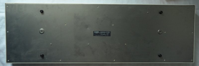
| removal of these screws voids warranty... | ||
 |
||
|
|