 |
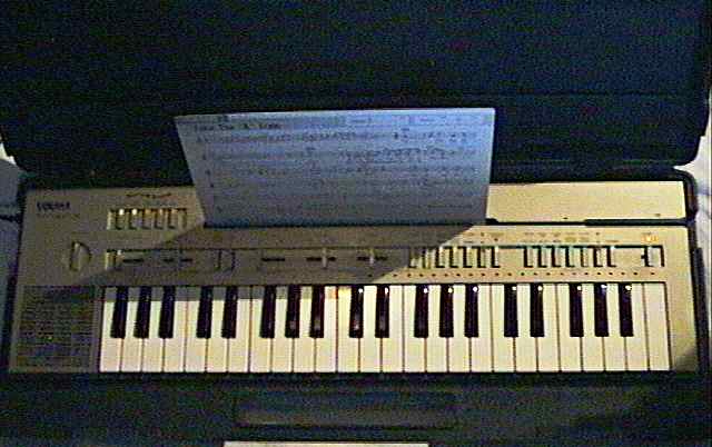
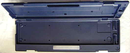
This is the instrument in its carry case. |
|
|
This is the instrument in its carry case. |
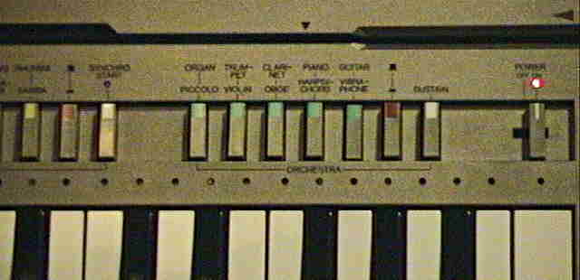
The main voice preset sounds are cold and very bright and resemble simple 2 operator FM sounds; interesting is the cheesy "vibraphone" sound which has slow tremolo. The single finger accompaniment has a nice arpeggio. The rhythms employ blip percussion of quite unique electronic style with semi- metallic hissing cymbals (a bit like Casio SK-1) and may be interesting for tekkno. The original German retail price of the PC-100 was 990DM (about 445€). Beside gold metallic also an ultra-rare dark brown woodgrain version was made (seen on eBay).
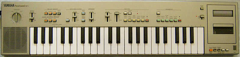
Above the keys are the key lighting LEDs. At the top is the PlayCard slot. |
 |
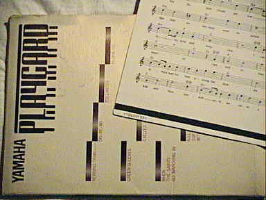 |
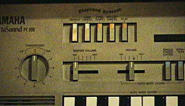
This is a PlayCard; much like a MIDI file the data tape strip contains the music data. |
The "organ" is rather Hammond than church style; it quickly grows slightly duller during its percussive attack phase (likely by crossfading 2 waveforms). The "piano" sounds more like an electric than acoustic one and the bass range strongly resembles a gently picked nylon guitar; "harpsichord" sounds much more realistic. The "trumpet" sounds way too thin and harsh. "trumpet", "violin", and "oboe" have a delayed 7Hz vibrato. "guitar" attempts to be a bright acoustic one. The "vibraphone" has a strong and cheesy sounding 3Hz tremolo, includes sustain and ignores the sustain switch. All other sounds stop almost immediately after key release when sustain is not pressed.
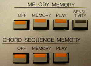
The single finger chord mode employs an envelopeless electronic organ
chord timbre, while the automatic accompaniment during rhythm plays a kind
of piano chord made from the same waveform with decay envelope, combined
with an e-bass. In manual chord mode the variation button toggles between
a very bright and a less bright organ timbre or vice versa depending on
the selected rhythm. (There are 2 chord timbres in total, those are also
used by the accompaniments.)
hardware detailsAll sounds including percussion are generated digitally by the YM1019 (GE4) sound IC and output through a 10 bit resistor ladder DAC and 3 additional volume control bits to scale the output. The obligato voice however is generated in the PlayCard CPU YM1020 (IE) and filtered in the analogue IC IG06110 (IEF), which also amplifies the tape head signal. The IE also polls PlayCard button group, controls key LEDs and handles song data in SRAM. For this it communicates with the main CPU and sound IC through serial lines. (I haven't examined the hardware, but read the service manual.)Initially I expected that there was a hidden sequencer easteregg in it, because the hardware used for PlayCard reading and playback (RAM etc.) is technically almost the same like a sequencer. How ever I later found out that keyboard variants with actual sequencer (like Yamaha MP-1) have a different main CPU and especially instead of the PlayCard CPU YM1020 an 80C85A with external ROM, which reduces the chance of its existence. If present, a hidden sequencer feature might even be capable to save data onto PlayCards, which would explain why Yamaha disabled or removed it to prevent users from accidentally overwriting their precious pre- recorded cards (or to avoid disturbing Yamaha's own PlayCard sale interests). At least the KAP serial line /SO1 outputs also 4 unused "sequencer" bits (seen in service manual), which hints that the main CPU can support a sequencer. The Yamaha ICs mainly communicate through 3 serial data lines /SI1, /SO1, /SO2. According to service manuals, many bits are not digital numbers but flags those (when hi) indicate whether a certain button is pressed or function is active at the moment. So each time slot after the /SY sync signal stands for one function flag or cipher bit. But the KAP sends the note key codes (those differ when transposed) also parallel to the GE4, which may be done to reduce latency. The service manual info looks complete enough to design a MIDI interface using these lines. caution!: The key matrix and serial data high level is +9V, which can be dangerous to TTL components when shorted for circuit- bending. So always use high resistors during experimentation, followed by 5V zener pulldown diodes against GND to avoid damage. note: In service manuals Yamaha uses "negative logic" terminology (exchanges the terms "ground" and "supply voltage") and often unintuitive pin function names (like "initial clear" for "reset"). I try to use here standard names and positive logic to avoid confusion. PlayCard data formatNowadays PlayCards are not made anymore; it would be interesting to find out the data format to make own PlayCards from MIDI files. Unfortunately Yamaha patented every tiny aspect separately instead of keeping everything in one text. An early key lighting algorithm is in US patent 4378720. The PlayCard system is described in the US patents 4413545 (basic idea) and 5144875 (as key lighting keyboard), the algorithm concept (unfortunately no details) in 4466324 and 4454797. Patent 4387620 reveals that the algorithm uses subroutines for repeatedly played parts of the song to conserve memory. Patent 4587878 describes the chord data. Patent 4406203 hints that data word lengths of musical notes is chosen by use frequency (like ZIP compression), i.e. the file contains a list renumbering all notes instead of using (like ASCII) always the same code for each of them (and every song is transposed to C); this would be surely hard to figure out without patent text. Beside the main voice, PlayCards contain also an additional obligato voice - so the PC-100 plays them often with more complex accompaniment than the normal built-in ones. I guess the very plain hardware of Yamaha PCS-30 is best suited to reverse- engineer the algorithm. Also the Yamaha MK-100 had a sequencer that can save its data on audio cassettes; possibly there are technical similarities in the data format. Has anybody more information on this?pinout YM1032 (KAP)The "Yamaha YM1032" (40 pin DIL) is the "KAP" main CPU of the Yamaha PC-100 keyboard (and possibly others). It contains internal ROM with rhythm and accompaniment patterns, polls the keyboard matrix and tempo potentiometer, and controls the external sound IC YM1019 (GE4). (Pinout is based on Yamaha PC-100 service manual.)
pinout YM1020 (IE)The "Yamaha YM1020" (48 pin DIL) is the "IE" PlayCard controller CPU, which was used in 1980th Yamaha keyboards with PlayCard system. It reads PlayCard data from the tape head into external sequencer SRAM, polls the PlayCard button group, controls key lighting LEDs, handles song data in the SRAM. For this it communicates with the main CPU and sound IC through serial lines. It also contains the obligato sound generator. (Pinout is based on Yamaha PC-100 service manual.)
pinout YM1019 (GE4)The "Yamaha YM1019" (40 pin DIL) is the "GE4" sound IC, which was used by Yamaha in many digital pre-FM keyboards of early 1980th. It outputs digital audio through a 10 bit resistor ladder DAC. Like Casio'sHD43517 it uses outside the main waveform 3 additional volume control bits to scale the output. (Casio even patented this as US patent 4414878.) The 8 note polyphonic sound generator layers 2 static digital waveforms with independent envelopes and generates blip percussion. It also polls the control voltages of channel volume potentiometers (rhythm, chord, arpeggio) and is designed to be controlled by a Yamaha "KAP" CPU (or variant like KAP2). The protocol (in service manual) looks like when preset sounds are selected through only 4 bits, thus they seem to be entirely predefined inside GE4 and can not be edited by synthesis parameters (which would make this chip boring). How ever some unused bits may still contain undocumented features. (Pinout is based on Yamaha PC-100 and MP-1 service manuals.)
pinout iGO6110 (IEF)The "Yamaha iGO6110" (16 pin DIL) is the "IEF" PlayCard helper IC of Yamaha PC-100. It contains the analogue filter for the obligato voice and the preamp for the tape head signal. (Pinout is based on Yamaha PC-100 and MP-1 service manuals.)
pinout iGO65310 (GEF)This is simply an analogue low-pass filter IC, used to remove HF ripple behind the DAC.
|
A white PC-100 variant with slide switches instead of push buttons was later released as Yamaha PC-50 (seen on eBay). 2 variants without PlayCard reader (and no key lighting) were made as Yamaha PS-400 and PS-300 (I read the manual). The black PS-400 had a chord sequencer, 4-bar rhythm variation switch and duet mode. The beige PS-300 (with beige carry case) has far less features; it has only 37 keys and 8 preset sounds and is missing many features like the chord sequencer, chord variation, transposer knob, duet mode and even lacks the arpeggio. (The Yamaha PS-500 looks identical and Yamaha PSS-401 seems to be a golden 44 keys variant of it.) These instruments were likely intended as digital successors of the analogue Yamaha PS-2 and PS-3. Also the Yamaha PS-200 from 1984 seems to be a black PS-300 variant with slide switches instead of push buttons and 3 built-in demo melodies. A very rare fullsize keyboard with PlayCard system was released in 1983 as Yamaha PC-1000 (49 keys, metallic with dark control panel, case style like Yamaha PS-55 but only 1 speaker | I own one.). Its main voice resembles Yamaha MK-100, while the percussion employs medium resolution samples similar like Casio SK-8. In 1984 the larger PlayCard keyboard Yamaha PCS-500 was released as successor of the PC-100; it featured 49 midsize keys, stereo symphonic (rotary speaker simulation), fingered chord and warmer sound, but unfortunately has no arpeggio anymore. A small PlayCard keyboard with only 32 keys and squarewave sound was released as Yamaha PCS-30. Later Yamaha released some ROM based key lighting instruments like e.g. the small TYU-30.
A PC-100 without keys came out as the "Synthesizer Card Player" Sanyo DP10, which was likely meant as a karaoke-like sing-along device with 2x microphone + aux jack and echo circuit. Although Sanyo omitted the preset sound switches and renamed some controls (e.g. "tone" for "transposer"), it has the same rhythm button set and also the sound (seen on YouTube) is blatantly similar. The DP10 was solely a music player for PlayCards without any means (no midi) to create own contents.
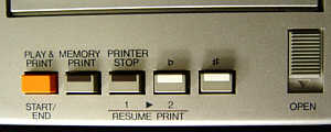
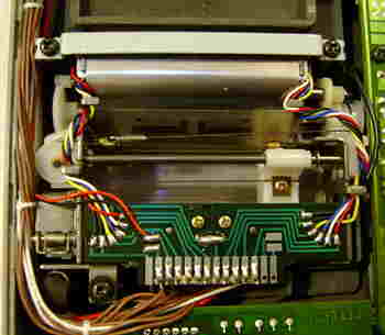
This keyboard was a close variant of the Yamaha PC-100, but instead of the PlayCard key lighting feature it had as the world only such midsize keyboard a built-in musical score printer.
This printer is a small plotter that draws music notes on a narrow paper strip using a small ball pen. It either prints immediately all played notes, or prints the recorded contents of an internal sequencer. There is also an additional duet mode and much like Yamaha PS-30 it has a stupid "4 bar" button switch that automatically inserts a rhythm fill-in every 4th bar; a manual fill-in button would have been much more useful here. Due to the strong similarity I only mention the differences to the PC-100 here.

 |
 |
 |
 |
 |
 |
 |
 |
 |
 |
 |
 |
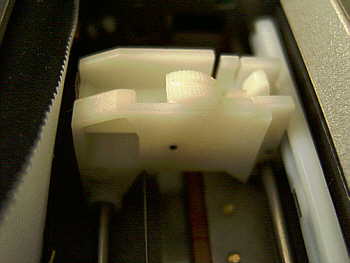
hardware detailsAlthough the MP-1 strongly resembles the Yamaha PC-100, it has a physically bigger main CPU YM1034 (KAP2) and instead of the YM1020 (IE) it has a sequencer based on a standard SMD CPU 80C85A with separate 32KB ROM and 6KB SRAM. The plotter is controlled by the MPU Hitachi HD44820A71 (named "DLG1103" in service manual) that communicates with the sequencer CPU. HD44820 is a known part, but with special ROM contents.Quite similar hardware was used in the Yamaha PS-400, but it has no plotter and MPU, no RAM and a different sequencer CPU "TMP80C39P-6" (40 pin DIL, romless Intel MCS-48 variant with 128 bytes RAM) using the 4KB external ROM "TMM2332P" (24 pin DIL, part no. iG078500 | seen in PS-400 service manual). The score printer algorithm is described in the US patent 4485716. I haven't analyzed this hardware by myself, but Scott Nordlund made a great hardware analysis of it. This is what he wrote (slightly edited by me): "I just got an MP-1 a few days ago (serial number 017836) and I spent some time checking it out. Hope you find this interesting:I later found the service manual to identify the main ICs. I see no IG07806 anywhere. There is only an address latch (IGO78600 = TC40H373P) between sequencer CPU and RAM/ ROM. caution!: The key matrix and serial data high level is +9V, which can be dangerous to TTL components when shorted for circuit- bending. So always use high resistors during experimentation, followed by 5V zener pulldown diodes against GND to avoid damage. note: In service manuals Yamaha uses "negative logic" terminology (exchanges the terms "ground" and "supply voltage") and often unintuitive pin function names (like "initial clear" for "reset"). I try to use here standard names and positive logic to avoid confusion. pinout YM1034 (KAP2)The "Yamaha YM1034" (64 pin DIL) is the "KAP2" main CPU of the Yamaha MP-1 and PS-400 keyboard (and possibly others). It contains internal ROM with rhythm and accompaniment patterns, polls the keyboard matrix and tempo potentiometer, and controls the external sound IC YM1019 (GE4). (Pinout is based on Yamaha MP-1and PS-400 service manuals.)
The KAP2 is a close relative of the PC-100 KAP CPU with additional pins. |
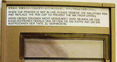
Question: Can anybody tell me what the original plotter ball pen for Yamaha MP-1 looks like? I want to replicate one.
With my Yamaha MP-1 someone had stuffed
a cylindrical lump of tar-like dirt into the tuning trimmer hole. I first
thought it was the remain of the plotter pen, but according to the instruction
sticker on the plotter lid a ball pen was used for it. Someone e-mailed
me that also his Yamaha PC-100 had
the same sticky stick in its trimmer hole, and after a close look even
at my PC-100 trimmer hole I discovered some black smeary stains from it.
Thus it was apparently originally placed there by the manufacturer and
not just stuffed in by a kid - likely some kind of plug that was originally
made of a wrongly mixed or accidentally unvulcanized rubber compound that
turned into pulp after few years. I only know that my Yamaha
PS-20 and PS-30
had badly smearing dissolved black foam rubber pods at their case bottom.
However I don't understand why anybody should plug a trimmer hole tight
with a soft material at all. It might be that the case was painted after
assembly (which makes very little sense) and the soft plug though should
protect the electronics against paint, and the manufacturer forgot to remove
it. Someone e-mailed me that his MP-1 also had this tar lump.
| removal of these screws voids warranty... | ||
 |
||
|
|