PS-30 PS-20 |
wonderful
analogue keyboards with accompaniment & arpeggio
...don't
call it PortaTone.
|
|
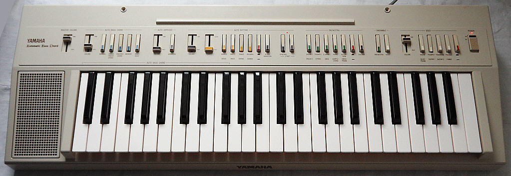
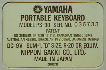
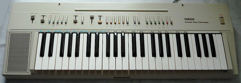
These instruments from 1981 were the first portable fullsize instruments with versatile "auto bass chord" accompaniment and belong to the last analogue keyboards created by Yamaha. Their novel plastic case made them much more lightweight than previous wood and metal constructions (and also contemporary fullsize Casios). Technically they were based on the Electone CN-70 organ of 1979 and have nice semi-analogue timbres, arpeggio and unusual semi-analogue percussion (resembling PortaSound PS-2). Unlike Yamaha's purely digital later models, the relatively open hardware architecture makes them nicely suited for modifications.
 |
 |
An even rarer black version was released as Yamaha PS-30B (seen on eBay).
 (picture taken from
eBay)
(picture taken from
eBay) |
 |
 |
  |
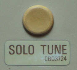
no PortaTone name found... |
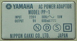 |
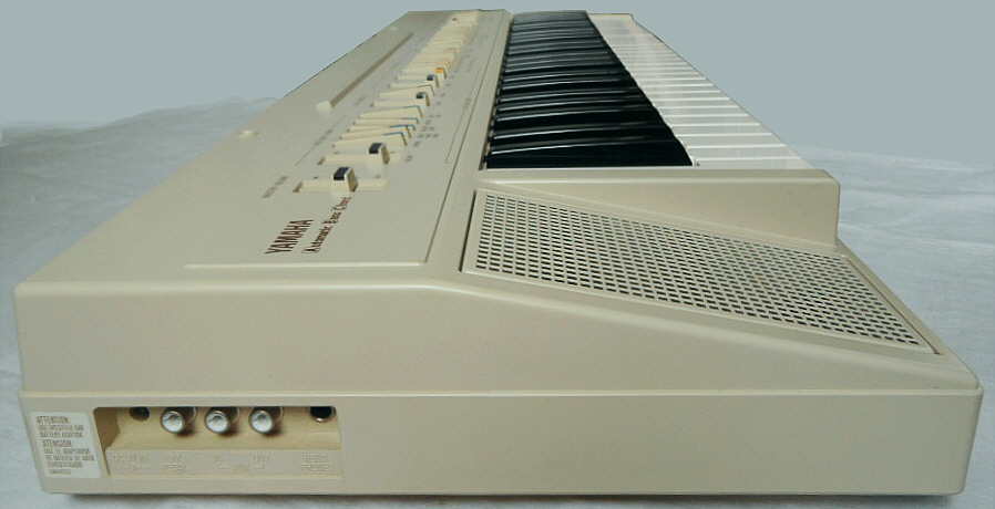
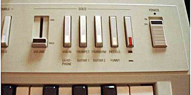
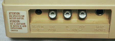
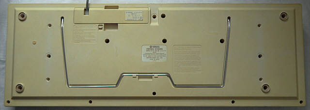
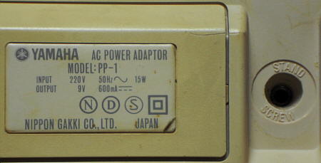
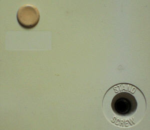
In the case bottom is a groove to store a metal bow that can be used as a note stand. Like with the Bontempi Minstrel Beta, instead of a battery holder (mine is missing) a special power supply module PP-1 can be inserted into the battery compartment. Very bizarre is that the volume and tempo sliders work "wrongways" (like organ drawbars), i.e. pushing them up makes sounds quieter or tempo slower, while pulling them down makes sounds louder and tempo faster. Likely sound mixers and graphic equalizers were so uncommon at that time that the control panel designers didn't come in mind to standardize this. Also the locking switches have an odd shape; they have a pivot at their rear end and tower up only with their front end when not pressed. I never saw such buttons at any other keyboard; possibly their design was inspired by piano keys. Also the golden "YAMAHA" logo at the front edge below the keyboard looks noble and piano- like.
The polyphonic "orchestra" preset sounds of the PS-30 feature many different vibratos; unlike in Yamaha PS-2, the vibrato of "trumpet", "string" and "oboe" are delayed and fade in only after the sustain phase of the envelope begins, and even the accordion has a very shallow version of this vibrato. The "organ 2" has an undelayed medium speed vibrato, and the "vibraphone" has a rather strong and much slower vibrato. When a key is trilled with sustain, each new note occupies a new sound channel, which produces a great phasing sound and volume increase effect although this eats up polyphony. The sounds are based on 4 layered squarewave tones those are post- processed by different analogue filters, but unlike many early Casio keyboards with filtered squarewaves, the tones of this instrument are not just muffled duller but differ a lot in timbre, and regarding the technology they are even reasonable realistic. Only in the bass range many sounds turn into a more or less buzzy, sonorous purring drone, but this is a characteristic style element of squarewave based instruments. Such basses can resemble some of the famous POKEY sound effects on Atari XL homecomputers and are very different from the gradually duller and duller growing sine wave bass behaviour of average Yamaha FM keyboard sounds, but unlike e.g. Casio MT-60, the PS-30 features no really dry and creaky bass timbres but plays rather round and sonorous ones. Particularly the "organ 2" has a wonderful "black", droning squarewave bass, which is likely also enriched by the zipper noise of its digital vibrato. The "organ 1" sounds like a reed organ. The "trumpet" is duller(!) than "string" and should be better labelled "cello". The "piano" is a little dull and the "harpsichord" is harsh, a little thin and suffers from a slightly too slow attack rate which makes the envelope less credible. The "vibraphone" otherwise is a highlight of this instrument; it sounds great and (besides bass range) astonishingly realistic, although its sustain can not be turned off. The "oboe" sounds thin, but that is what it should. Also the "clarinet" is ok.
The "solo" preset sounds can be layered with the "orchestra" sounds. The solo sounds are only monophonic but include an analogue VCF with decay envelope, which permits more realistic and expressive timbres. E.g. unlike above, the "trumpet" here really resembles what it was supposed to be. The trumpet and trombone fade duller and include delayed vibrato. Also both guitars fade duller; "guitar 1" is a dull one while "guitar 2" has a brighter timbre with some vibrato. The violin also employs delayed vibrato and sounds quite realistic. The saxophone has a mild, delayed vibrato. The "piccolo" is a sweet analogue tone with quite strong vibrato, that fades slightly duller; it doesn't sound really like a flute, but almost voice- like and resembles more a theremin or singing saw and gets a little brassy in the bass range; this cute and cheesy analogue timbre is definitely one of the great highlights of this instrument. The "funny" sound is a sort of e-bass with tuba timbre that fades brighter and has a strong vibrato. Interesting is that also in many early Casio keyboards (see Casio MT-60, CT-410V, MT-70, MT-30) sounds with "funny" in their name exist. The sustain button affects only the orchestra section but not the solo voice. There is a separate solo volume control and 2 "ensemble" switches to enable solo and/ or orchestra section separately. Unfortunately the solo section can not be used for a key split mode but only layered with the rest.
The semi-analogue percussion sound a bit dull, but has an unusual timbre. The base is just a dull and quiet "pop" noise (like heard in the speaker when switching a radio on) consisting of 2 pulses muffled by a capacitor. The 3 tuned drums (bongo + 2 congas made of grainy digital sines) have a strange timbre like drumming on plastic bottles. The hihat is based on a similar semi- digital technology like in Yamaha PS-2 and sounds a bit more metallic than the analogue transistor noise hiss found on other electronic percussion of that era. With the "8 bar variation" switch, an automatic fill- in is inserted every 8th bar of the rhythm; a manual "fill-in" button would have been much more useful. The default tempo settings of the individual rhythms vary quite extreme (caused by different internal pattern resolutions?). Likely to compensate this, the range of the tempo slider is quite wide, thus it needs to be tweaked with care because the tempo reacts audibly already on very small changes. In spite of this, the maximum tempo of some rhythms can not be set really high.
The "chord memory" switch makes simply that current chord is held after
releasing the chord keys (this is no sequencer), but unusual is the way
how rhythm and chord memory interact. The rhythm is activated here by 2
different locking switches; when only "start" is on, rhythm plays always
and independent from the chord section. When also "synchro" is on, rhythm
is started as soon a chord key is pressed, and then keeps playing until
rhythm is switched off. But when only "synchro" and not "start" is on,
then the rhythm pattern starts as soon any chord keys are pressed, and
so far chord memory is off, the rhythm stops each time you release all
chord keys; this permits interesting improvisations e.g. by trilling on
chord keys. This odd mode I yet only found at a single other and also very
old keyboard, namely my Bontempi
Minstrel Beta. Unlike the latter, the chord memory here works only
with the automatic accompaniment and not in organ chord mode (with rhythm
stopped). In fingered chord mode the accompaniment plays the more notes
the more keys are pressed, and this works even perfectly with all key combinations
(up to 4 keys) and not just the few ones establishment has defined to be
"chords", which permits very versatile accompaniment sound patterns. (This
flexible behaviour is absolute no matter of course, see the later Yamaha
PSS-390 for an annoyingly stubborn example.) The "multi bass" button
changes the accompaniment; with most rhythms it makes a walking bass pattern.
When no rhythm is selected, the instrument plays instead of accompaniment
plain organ chords with a fixed timbre and a little sustain. The arpeggio
has a decay envelope (like a harp) and the notes it plays change by the
currently pressed accompaniment keys (but the count of notes stay the same).
Its variation switch switches with most rhythms between a 16 step and an
8 step arpeggio pattern; only with "rhumba" it changes the speed.
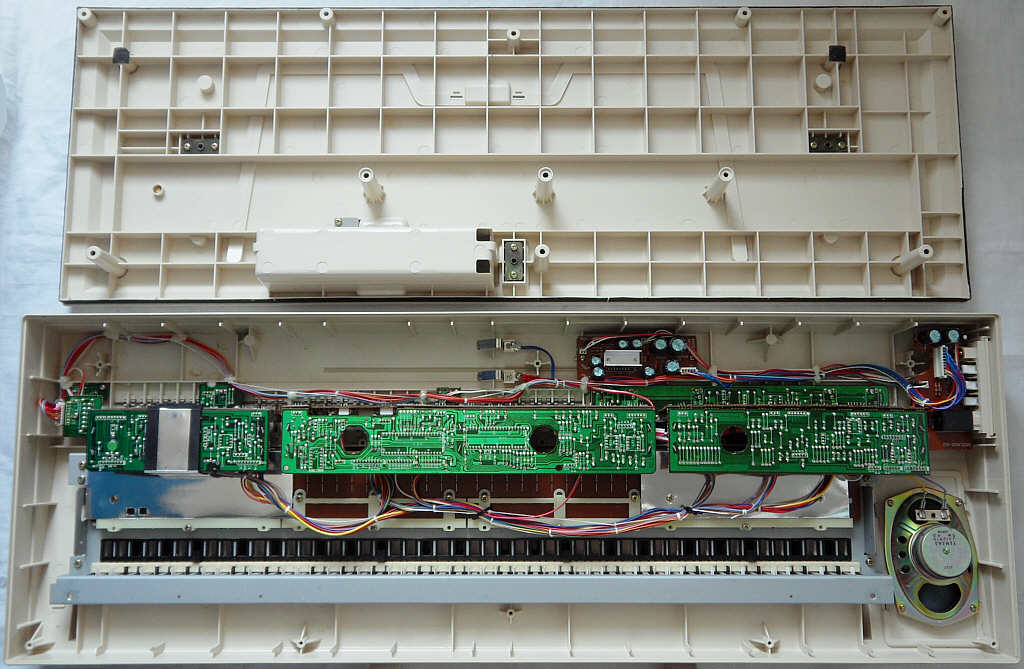
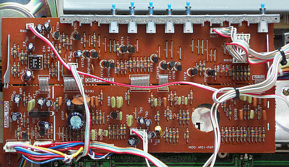
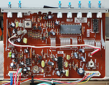
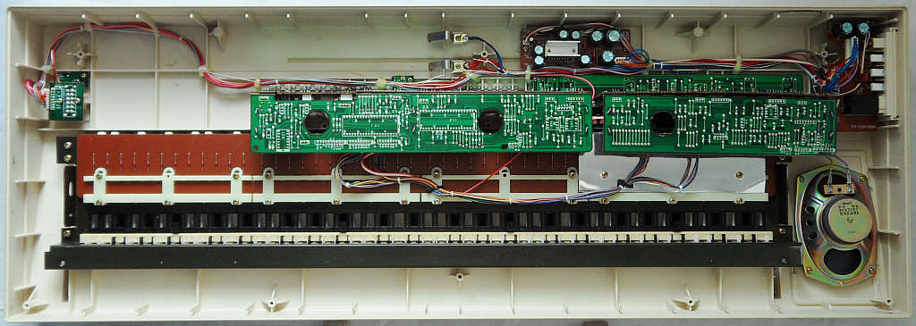
circuit bending detailsThe Yamaha PS-30 and PS-20 both employ fairly complex semi-analogue hardware built around the CPU YM1011 (KAR) and main sound IC YM1101 (DOM). The PS-20 is a variant of the CN-70 home organ (released already in 1979, 61 keys, only 5 preset sounds). The PS-30 has an additional solo voice PCB with monophonic sound IC YM1102 (SOM) and VCF IG02611. This hardware is closely related to Yamaha Electone home organs of its era, so it consists of several small and well marked PCBs, those are nicely suited for modification.I haven't modified this instrument yet, but this is what I found out. The following descriptions relate to the instrument opened and placed keys facing down with view at PCB solder side. The bulky plastic case is mainly empty; there are only 4 small main PCBs in it those would likely also fit into an average PortaSound. The German language PS-20 service manual mentions that it is based on PAS (Pulse Analog Synthesis) system technology, which was Yamaha's marketing term for digitally controlled semi-analogue sound synthesis (used mainly in Electone organs and synths). The hardware architecture is (unlike digital later Yamaha keyboards) well suited for systematic sound modification. But do not expect to find a CS80 synth hidden inside of it. This is a relative of the single keyboard organ CN-70 of 1979 (often used in music schools), thus the main voice timbres are still only a mixture of 4 digital squarewave drawbars with analogue envelope, routed through fixed analogue filters.
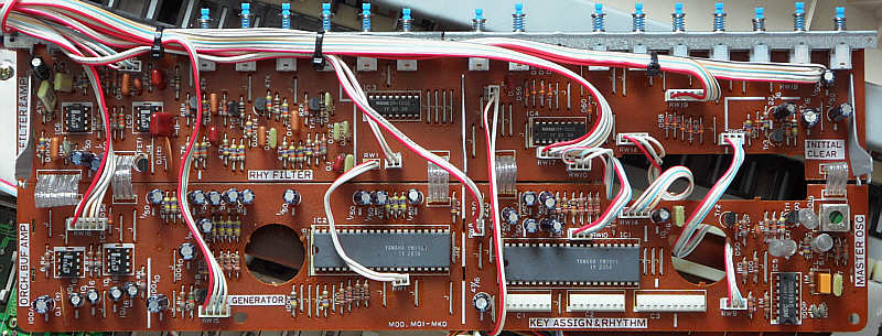
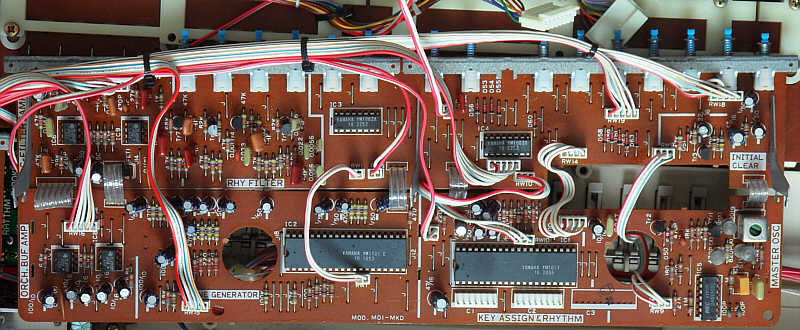
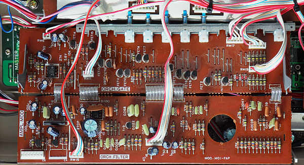
The main units are divided in a horizontal and a vertical PCB section (with panel switches) connected with transparent ribbon cables. They are held on their sheet metal frame by bent tabs those need to be straightened for removal. The below pictures show these PCBs removed and laid out flat.
Many functions (e.g. preset sounds) in the behaviour of this early analogue instrument are mainly controlled by the wiring of PCB traces and not hardcoded inside ICs, thus with some skill it can be likely upgraded to a versatile analogue synthesizer. So I finally found an original service manual of Yamaha PS-20 (with German language function description), which explains much about the hardware and data protocols, but unfortunately (of course) lacks the solo voice description. Interesting is that it mentions similarities with Yamaha PS-10, which is basically a fullsize PS-2 with simpler single-chip CPU YM1104. sound generatorThe main voice sound IC (DOM) outputs only 5 internal preset raw sounds made from 4 squarewave footages {2', 4', 8', 16'} with volume envelope, those (like organ drawbars) are externally mixed and post- processed by switchable fixed analogue filters to form the final orchestra preset timbres. Unlike analogue PortaSounds, these footages are indeed each a plain squarewave (1:1) and do not change in any way by the selected raw sound; only their volume envelope and vibrato differs. The raw sounds are an organ sound (with short attack and release envelope, in 3 variants with different vibratos), a harpsichord sound and a vibraphone sound (with slow vibrato). Sustain decays always with the same speed. The vibrato uses an LFO pin to modulate the pitch clock with a digital sinewave. Depending on preset sound, vibrato can be delayed, i.e. amplitude stays 0 during attack and slowly grows to the final level (where it also stays after note-off). Unlike in later Yamaha instruments none of the audio outs employ a timeslice DAC. (On oscilloscope I found no chopped waveforms.)Each of the 10 main voice channels has its own envelope capacitor. With chord or accompaniment 6 of them are re-routed as bass, chord and arpeggio voices. Due to negative logics, by the volume envelope not the "1" blocks move up, but the "0" move down (so the whole principle could be considered inverted). The bass, chord and arpeggio voice are made from squarewave with apparently 3:1 duty cycle and have each an own output. The semi-analogue percussion is output by the CPU (KAR) and has more individual pins than in analogue PortaSounds. Interesting is that percussion has a separate clock and so stays unaffected by vibrato. The 'base' and the knock part of 'snare' are exactly what they sounds like - namely a short digital squarewave pulse without envelope, making a pop noise like powering on an old transistorized radio. Possibly these were originally planned as 2 trigger pulses for omitted analogue drums. The 'hihat' and 'snare' (hiss part) are made from each a semi-metallic digital waveform (likely shift-register feedback noise) and have each an envelope capacitor. The 'hi bongo' and 'hi conga' are a digital wannabe sinewave with grainy 4 step (2-bit) resolution; only the 'lo conga' has 7 steps (3-bit). Unlike PortaSound, they all have separate envelope capacitors and thus do not mix into that strange bottle clang when they sound at the same time. The envelope capacitors can be also triggered externally (pulling lo through e.g. an 1k resistor). solo voice sectionThe monophonic solo voice of the PS-30 is output by the SOM sound IC. All sounds are made from either a 4-bit falling sawwave or a squarewave with 7:1 duty cycle with different vibrato, those are routed through a voltage controlled filter IG02611. So they can have different volume, cutoff and resonance envelope to form 8 solo preset sounds.
SOM pin 13 seems to be filter resonance envelope and pin 17 cutoff envelope out. Pin 12 seems to be a VCF audio input and also related to resonance (high resistance and very hum sensitive). But I haven't fully investigated how it works. The filter definitely can sound good and makes some wicked tekkno noises when controlled properly. With some upgrades the PS-30 can be certainly modded into a synth roughly like Yamaha SY-1 (plus percussion & accompaniment). synthesizer featuresI haven't analysed this instrument closer yet, but the sound select buttons of this instrument work similar like in Yamaha PS-2 (see there) and thus can be likely modified similarly. But unlike PS-2, the panel switches are not part of the keyboard matrix, but are directly connected to each a separate pin of 2 I/O ICs YM1002 (PSC II) those convert them into serial data to the CPU YM1011 (KAR). In PS-30 the solo section has a 3rd PSC II connected to its YM1102 (SOM).Because the sound IC YM1101 (DOM) outputs 4 separate squarewave organ drawbar tones, it is likely easy to add 4 potentiometers here to mix your own timbres. By adding a switch with a diode from +Vs to the vibraphone output (sound IC pin 13), the vibraphone vibrato can be enabled in all sounds. This vibrato seems to contain even a mild chorus effect to enrich the timbre. The LFO output to the pitch clock oscillator is DOM pin 14, where certainly a vibrato depth potentiometer or even external LFO can be added. As usual with analogue drums, the percussion is also easy to modify. The IC3 "1G02611" of the solo section is the VCF (voltage controlled filter). This is a close relative of the chip in Yamaha CS-01. It is connected with multiple external capacitors and the filter envelope reacts sensitive when the IC is touched by hand, thus it can be likely upgraded easily with additional pots to change the filter behaviour. The SOM seems to output envelope control voltages for cutoff (pin 17) and resonance (pin 13?) and outputs its unfiltered waveform at pin 19. There is also an audio feedback loop(?) at pin 12. Pin 18 is the volume envelope cap and pin 20 a cap for the attack pulse of the filter. I haven't fully investigated how the VCF works. But it is undoubtedly possibly to install switches to feed it with external audio (e.g. from main voice, chord or percussion) and control the envelopes externally, to make of it something like Yamaha SY-1 or (closer) Casio CT-410V. Richard Atkinson has thoroughly examined this chip in Yamaha CS-01 and wrote how to mod that. (Attention: I have neither modified nor fully analyzed this instrument yet, thus I can not guarantee that the above instructions are correct. Especially the SOM pinout may contain errors.) keyboard matrixThe keyboard matrix of this early Yamaha is quite unusual. The matrix lines of the CPU (KAR) only handle piano keys. The matrix is grouped by 6 and has 2 cable connectors. Connector "C1" contains 7 output lines labelled N1..N7. Connector "C2" contains 7 input lines labelled {B11, B12, B21, B22, B31, B32, B41, B42}. (The strange numbering counts semi-octaves. B stands for block, N for note.) The inputs react on + 9V. This matrix is based on Yamaha PS-20 service manual and my own examination of the solo voice wiring.
The input lines are active-high, i.e. react on +Vs. Any functions can be triggered by a non- locking switch in series to a diode from one "out" to one "in" pin. The control panel switches are not in a matrix but wired from each a
separate pin of "PSC II" ICs to +Vs, those send switch settings as a loop
of serial data to the KAR. The unused PSC II pins do nothing, so there
are no eastereggs.
The locking preset sound switches select through a diode among only 5 raw preset sounds, but have additional diodes to select through FETs fixed analogue filter settings. The 'vibraphone' switch this way also enables sustain. Their switch contacts are daisychained in a way that if multiple switches are pressed only the rightmost takes effect. But (unlike PS-3 etc.) the voltage control concept through diodes (hi=on) is very straight forward and easy to modify. On solo voice PCB, the 'solo voice' switch feeds voltage to all related
preset sound switches. The orchestra switch goes to its C1 connector pin
16 'EMS'. The solo voice switches set no fixed filters, but only select
each a preset sound of the SOM, which changes cutoff and resonance envelopes
of the VCF to shape its timbres.
pinout YM1011, YM1001 (KAR)The Key Assigner & Rhythm "Yamaha YM1011" (40 pin DIL) is the CPU of Yamaha PS-20 and PS-30. The YM1001 is an older version, that needs a daughter board "TO3" at pin 37 (the YM1011 only a 82nF cap to VSS).The KAR polls the keyboard matrix and outputs data for the sound IC YM1101 (DOM). Additionally it produces digital waveforms and trigger pulses for semi-analogue percussion, those need external envelope capacitors and are routed through external fixed timbre filters. The 'hihat' and 'snare' (hiss part) are made from each a semi-metallic digital waveform (likely shift-register feedback noise) and have each an envelope capacitor. The 'hi bongo' and 'hi conga' are a digital wannabe sinewave with grainy 4 step (2-bit) resolution; only the 'lo conga' has 7 steps (3-bit). Unlike analogue PortaSound, they all have separate envelope capacitors and thus do not mix into that strange bottle clang when they sound at the same time. In CN-70 schematics (not its text description) this IC is depicted as YM10010, which may be an alternative name of an even older version. caution: This IC uses "negative logic", i.e. technically +9V is its GND while 0V is its -9V supply voltage. So the voltages are not was the pin names suggest. I use the positive voltage naming convention (from 0V to +9V, not -9V to 0V). This pinout is based on my Yamaha PS-20 service manual.
Pin 28 outputs a very clear and metallic cowbell clang, which seems to be used only as a component of the bongo(?) sound although it sounds surprisingly realistic (may this have been Yamaha's first and unofficial use of an FM sound on a home keyboard?!?). The rhythm waveform outs respond with continuous tones when connected through a resistor with GND(?); these signals are sent through their envelope capacitors. The keyboard matrix ins (N1..N7) are notes, while the outs (B...) are octaves (B1x = lowest). So their strange numbering (Bx1, Bx2) was likely done to indicate both halves of the same octave. At the unused pins 21 and 22 are higher note keys addable. The KAR protocol reads 22 time slots of each 4-bit (data pins KC1..KC4) to scan all keys at a rate of 4.5ms, synchronized by a 2us hi pulse on pin 23. Any key press is transmitted as (word 1) a 4-bit note number, followed by (word 2) a 3-bit octave number + 1 bit "note on". pinout YM1002 (PSC II)The Parallel - Serial Converter "Yamaha YM1002" is a helper IC that handles control panel data. It reads up to 10 switch inputs and converts them (by internal shift registers) into serial data sent to KAP and DOM. Multiple YM1002 can be daisychained through their serial port when more than 10 switches need to be polled.In CN-70 schematics (not its text description) this IC is depicted as YM10020, which may be an alternative name of an older version. caution: This IC uses "negative logic", i.e. technically +9V is its GND while 0V is its -9V supply voltage. So the voltages are not was the pin names suggest. I use the positive voltage naming convention (from 0V to +9V, not -9V to 0V). This pinout is based on my Yamaha PS-20 service manual.
Pin 2 is described "serial data IN <= PSC II"; in PS-20 schematics the last one is wired to VDD (grounded), so this is likely a daisychaining mechanism to connect multiple YM1002 for handling a large control panel. The protocol is simply a loop of bits (each 2us), those are hi for every enabled switch. The bits are shifted out in reverse pin order (P10, P9, P8,..., P1 followed by P10 etc. of other PSC II at its /Si pin). The sequence repeats every 47us and is synchronized by a 2us hi pulse on pin 1. If anybody wants to control the sound synthesis by a microcontroller, this port would be certainly the best place to add it. Of course voltages need to be converted to the strange 9V level. pinout YM1101 (DOM)The Digital Tone Generator "Yamaha YM1101" (40 pin DIL) is the sound IC of Yamaha PS-20, PS-30 and related Electone organs like CN-70. It outputs squarewave accompaniment tones directly (using capacitor envelopes), but the up to 10 note polyphonic main voice is output through 4 individual pins as 4 separate, polyphonic squarewave tones (labelled with organ pipe footage names {2', 4', 8', 16'}) including envelope. The result is mixed externally (additive syntheses like in a drawbar organ) to form the final timbres (those are routed through external analogue filters). E.g. some waveforms form a stairstepped sawtooth from squarewave footages. The delayed vibrato uses an LFO pin for external circuits (modulating pitch clock or VCA). As a real sound IC it has to be controlled by an external CPU through a 4-bit data bus.Unusual for a Yamaha keyboard is that this sound IC has no GE# number (e.g. PS-1 has GE1, MK-100 has GE7 etc.), which suggests that it is so old that it was originally designed for Electone organs rather than home keyboards. Despite PS-20, PS-30 were released one year after 1st generation PortaSound (PS-1, PS-2, PS-3), not least the related Electone CN-70 organ of 1979 (seen in CN-70 service manual) proves that the PS-30 hardware platform was developed first and later simplified to create those PortaSounds. In CN-70 schematics (not its text description) this IC is depicted as YM11010, which may be an alternative name of an older version. caution: This IC uses "negative logic", i.e. technically +9V is its GND while 0V is its -9V supply voltage. So the voltages are not was the pin names suggest. I use the positive voltage naming convention (from 0V to +9V, not -9V to 0V). This pinout is based on my Yamaha PS-20 service manual. The word
"data" in its pin description often seems to mean simply a switch or voltage
output for analogue functions (e.g. vibrato). I instead have renamed these
pin functions "control" where no actual digital data (binary numbers) are
transmitted.
The ciphers in audio out pin names indicate organ footages. The volume envelope levels vary among preset sounds to match the gain of their corresponding filter settings. Pulling test pin 2 lo through a resistor (reacts even on finger) increases pitch of any sounds/percussion and turns their tone scales into disharmonic mess. Test pin 3 seems to do nothing. Pin 9 turns hi while manual chord notes in chord section are played. It turns lo again when chord mode is switched off or accompaniment is sounding. This pin is used for 'level control' of a preamp that likely changes the volume of chord (organ tones) in ratio to accomp notes (with piano decay). The German service manual text tells that it can be also used to reliably sync an oscilloscope for examining data an pins 5..8. The unused pin 10 behaves similar, but turns lo while 9 is hi, and else is high resistance. Pin 12 (key-on) pulls lo while one or more melody voice keys are pressed. Else it stays high resistance. (The key-on pin of analogue PortaSounds behaves different; it outpute a short lo pulse during each additional melody voice key press.) Pin 13 turns hi while the 'vibraphone' preset sound is selected, which is used to set the analogue vibrato circuit. Pin 14 is the vibrato control voltage out, which outputs a digital sinewave LFO to modulate the sound source clock oscillator. Depending on the selected raw sound, vibrato can be delayed, i.e. amplitude stays 0 during attack and slowly grows to the final level (where it also stays after note-off). According to the service manual, during 'vibraphone' and 'accordion' the vibrato is routed to FET 14 to make the LFO perform amplitude instead of frequency modulation. (Initially I had written that connecting the audio pins 18..21 directly with the amp produced no tones. Possibly the signal has very high frequencies (the instrument makes no audible aliasing) - these may be simply PWM bit streams decoded by op-amps and capacitors, decoded by a strange kind of external DAC consisting of a few capacitors and op-amps IC6 and IC7 (both "Texas Instruments TL4558P, J104, LTJ", 8 pin DIL). According to the service manual these should be 4 normal analogue footage outs and not digital data. So this may have been an error by me.) pinout YM1102 (SOM)The Solo Tone Generator "Yamaha YM1102" (24 pin DIL) is the "solo voice" sound IC of Yamaha PS-30 and likely related Electone organs.It outputs monophonic waveforms with volume envelope for the solo voice and control voltages for an analogue VCF. As a real sound IC it needs to be controlled by a host CPU. Additionally it has a serial data input for an YM1002 (PSC II) for solo voice panel switches. Depending on selected preset sound, the raw waveform can be either a 4-bit falling sawtooth wave or a squarewave with 7:1 duty cycle. I had examined this pinout by myself, and pin names later corrected from Yamaha PS-30 service manual. caution: This IC uses "negative logic", i.e. technically +9V
is its GND while 0V is its -9V supply voltage. So the voltages are not
was the pin names suggest. I use the positive voltage naming convention
(from 0V to +9V, not -9V to 0V).
The unused pin 3 outputs a multistep spiky signal at about 1MHz (like the pitch clock). It is likely a test pin revealing internal data. Pin 9 turns hi while one or more keys are held. It is interrupted by a short lo pulse when an additional key right to it (plays new note) is pressed. Pin 11 (cap to AG1...) outputs a delayed vibrato control voltage (similar like in DOM YM1101). It outputs a digital sinewave(?) LFO to modulate the sound source clock oscillator. Depending on the selected raw sound, vibrato can be delayed, i.e. amplitude stays 0 during attack and slowly grows to the final level (where it also stays after note-off). Pin 12 (cap to VCF pin 11) seems to be an audio input or feedback line of the VCF. It is very hum sensitive when touched with fingers. It seems to be related to filter resonance and may be its coarse control. Connecting a 6 megohm potentiometer (for safety with 1k in series) to +Vs or to pin 13 made a quite rough and noisy resonance control, that can even drive it to self-oscillation. The VCF has a cap parralel with resistor from pin 11 to 12, from 12 another cap to 3 and another to 5, which appears to be a feedback loop for resonance. Pin 13 (cap to AG1...) seems to be filter resonance envelope out. The tone grows brighter when the control voltage falls. Pulling it too low (1k resistor to ground 0V) however makes it dull. Pin 16 (cap to AG1) is likely an analogue supply voltage. Pin 17 (cap to AG1...) seems to be filter cutoff envelope out. The tone grows brighter when the control voltage falls. Pulling it too low (1k resistor to ground 0V) however makes it darker. Pulling it high makes it brighter. I still haven't fully figured out how the filter control really works and what pin 12 exactly is. These are certainly no standardized CV voltages. But it likely wants to see a reasonably low resistance voltage (pot wired as voltage divider between +Vs and 0V or a fraction of that) rather than pulling with a very high resistor into only one direction. The filter definitely can sound good when controlled properly. Pin 18 (cap to AG1) is the volume envelope capacitor. Pulling it lo (1k resistor to ground 0V) makes the tone loud with plenty of nice analogue distortion like an overdriven e-guitar. Pin 19 outputs the raw audio (raw digital waveform with volume envelope and vibrato) to the VCF. Pin 14 and 15 seem to be audio (amplified solo voice including filter). 15 goes to the VCF, and 14 to IC4 (likely VCA). Pin 20 (cap to AG1) seems to be a filter cap for the attack phase of the filter resonance envelope. Pulling it with 1k resistor to ground 0V makes sounds attack harder. Pin 22 (resistor to Tr3, Tr4) seems to be the pitch clock (on oscilloscope 3.6*0.3us = roughly 1MHz, modulated with vibrato). pinout IG02590, IG02592, IG02595,IG02600, IG02602 (VCA)The VCA "Yamaha IG02602" (7 pin SIL) is a voltage controlled amplifier used in many analogue Yamaha instruments.This pinout is from my Yamaha PS-20 service manual. Also IG02600, IG02590 and IG02592 have that pinout (seen in those of CS-01 and C55-N), and also the IG02595 in my Yamaha PS-3 looks like yet another variant. Pin names are from IG02600 datasheet. But this thing is fairly trivial to understand anyway. caution: This IC uses "negative logic", i.e. technically +9V
is its GND while 0V is its -9V supply voltage. So the voltages are not
was the pin names suggest. I use the positive voltage naming convention
(from 0V to +9V, not -9V to 0V).
pinout IG02610, IG02611 (VCF)The VCF "Yamaha IG02610" (14 pin DIL) is the voltage controlled filter used in Yamaha instruments including CS-01 and Electone C55-N. The later variant "Yamaha IG02610" was used e.g. in PortaSound PS-3 and PS-30.It is hard to find any specs about this analogue part, but according to the service manuals of Yamaha CS-01 and CN55-N this is the pinout. Pin functions were concluded from those schematics and may be wrong. I don't know if this is only a quad op-amp in fancy camo to fool competitors or really something special. caution: This IC uses "negative logic", i.e. technically +9V
is its GND while 0V is its -9V supply voltage. So the voltages are not
was the pin names suggest. I use the positive voltage naming convention
(from 0V to +9V, not -9V to 0V).
The listed connections are from CS-01 and CN55-N and only examples to figure out what it does. Resonance is apparently a feedback loop from pins 11 and 12 back to 4, so this has no simple single control voltage pin. Possibly the slope (dB/octave) or mode of the filter can be even changed by different wirings. Richard Atkinson has examined this chip closer and thoroughly explained how to mod the Yamaha CS-01 synth. Likely similar principles can be applied to the PS-30 and PS-3. |
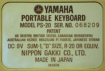
 (old eBay photo of my specimen)
 |
  |
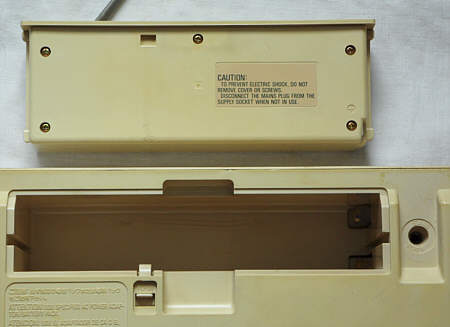 |
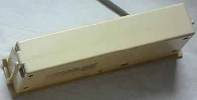 The power supply cartridge could be swapped with optional battery compartment.
 |
 |
 |
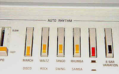 Such a dual colour button style on a beige case was also used on the Casio
MT-60, although its controls are rounder.
Such a dual colour button style on a beige case was also used on the Casio
MT-60, although its controls are rounder. |
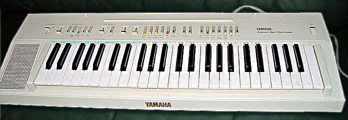
No solo-tune trimmer in PS-20 |
PS-20 lacks the solo voice pcb. |
 |
 |
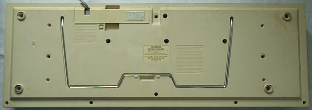
Caution: Both the Yamaha PS-20 and the PS-30 suffer of a really annoying disease; the foam rubber pods under their case dissolve into a tar- like, very sticky black goo. The only cure for this is to remove the black pulp from the pod holes at the bottom using a lot of Q-Tips and isopropanol (which still needs quite a lot of time), because otherwise it infests everything with black stains those at least on fabrics are almost impossible to remove. I had ruined a carpet floor with this stuff and could only get it out by rubbing it quite long with vegetable food oil and then removing this goo with concentrated liquid soap followed by plenty of water.
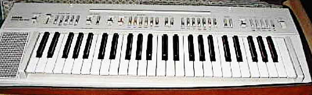
Possibly a fullsize PS-20 variant was the wooden home organ Yamaha
Electone CN-70 (1979, 61 keys, only 5 preset sounds). A shorter 44
keys case variant of the PS-20 with only 6 sounds, 4 rhythms and
far less features (no arpeggio...) was released as Yamaha PS-10,
but this is a totally different hardware class because it was instead just
based on Yamaha PS-2. Already in
1982 Yamaha abandoned the analogue technology entirely and thus
made all following keyboards only with strictly digital sound generation,
while Casio kept analogue percussion and filters in their instruments
far longer until the mid of 1980th. Nowadays the Yamaha PS-20 seems
to be fairly rare on eBay and the PS-30 even rarer. Successors
of these instruments were the Yamaha PS-55 (stereo) with the simplified
variants PS-35 (stereo) and
PS-25 (mono) from 1983, but these
boring rectangular silver boxes with bulky speakers left and right to the
keyboard were already digital (apparently relatives of
Yamaha
MK-100 hardware with sample percussion).
| removal of these screws voids warranty... | ||
 |
||
|
|