(old eBay photo; mine has no box.) |
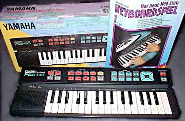
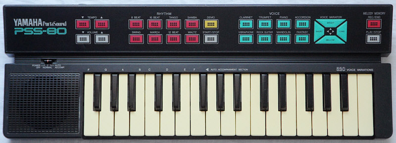
This Yamaha PortaSound keyboard from 1989 is quite unique, because
it combines coarse unfiltered multipulse squarewave sounds with a simple
synthesizer (320 sound variations), reasonable polyphony and grainy electronic
percussion.
|
(old eBay photo; mine has no box.) |
The whole thing sounds quite C64-like, but has its own character. E.g. there is a nicely unique squawky "trumpet" sound. Less nice is that decaying sounds ignore key press duration. The 8 rhythms are made from interesting semi-metallic blip percussion and have optional single finger accompaniment.
(Note: This keyboard sounds great, but don't buy one of these so far your only intention is to get a keyboard with faithfully imitated natural instrument sounds. Remember, this is a squarewave instrument and though many of its sounds sound not even remotely like what is written on its buttons, though bought with wrong expectation it may disappoint you.)
An even greater variant of the PSS-80 (that includes the same sounds, but has each 16 sounds & rhythms) is the Yamaha PSS-100.
| base & tom | = very low & slightly higher (squarewave?) pop noise |
| snare | = shift register noise |
| open cymbal | = unique electronic metallic timbre (low- res waveform sample??, or 2 mixed squarewaves?) with truncated decay and audible end click. |
| closed cymbal | = dto. with shorter envelope |
 |
 |
The sounds are digital multipulse squarewave with audible zipper noise (similar like the Letron/ MC-3). Decaying sounds like 'piano' unfortunately ignore key press duration. The 'clarinet' sounds normal. The 'trumpet' is most remarkable; it starts with a strange scratchy smack during attack (different waveforms), has a fast and strong vibrato and its harsh timbre is at least slightly more natural than trumpets on other squarewave instruments (roughly like a cupped jazz trombone). The 'accordion' is a simple squarewave toot. The 'vibraphone' has a slow tremolo with such a high amplitude, that with most volume and envelope settings it completely mutes the tone in the quieter phase. The 'rock guitar' is rather a thin and harsh organ tone that starts with a click and resembles bagpipes timbre. The 'mandolin' rings fast. The 'fantasy' is a sort of slower ringing mandolin which fades silent while it keeps ringing.
The "voice variator" synthesizer buttons {bright, mellow} change the pulse patterns of the square wave in 8 steps and thus permit to select any of the 8 existing timbres for the sounds. The {short, long} buttons permit to select among 5 different preset envelopes for each preset sound. Unlike the timbres, the 5 envelopes differ among the preset sounds, thus every sound has an own set of 5 envelopes. The longest envelope typically softens also the attack phase while the shortest envelopes reduce not only the decay phase but also the sustain level (with "fantasy" this disables ringing). The {bright, mellow} buttons also change the timbre of still held notes, while {short, long} only affect new pressed keys. Selecting a preset sound always mutes held notes and resets "voice variator" values to defaults. All button presses on the soft touch panel cause a blip sound, which limits their use as a realtime sound control.
The cymbal consist of a metallic digital waveform, similar like MC-3
cymbals. The base and tom drum are a very low and a slightly higher short
popping noise. The "16 beat" rhythm has an accent on the cymbal and "tango"
features a drumroll. Rhythms can not be switched immediately but always
wait until the pattern ends. The single finger accompaniment plays only
3 standard chords. The sequencer can be used to playback a monophonic voice
while playing to it. (Rhythm does not reduce polyphony, but sequencer playback
always starts the rhythm it was recorded with. The sequencer can not be
used without rhythm, and always plays with the sound that was selected
first during recording. The accompaniment is not recorded.)
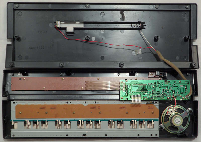
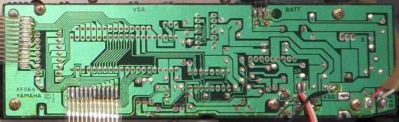
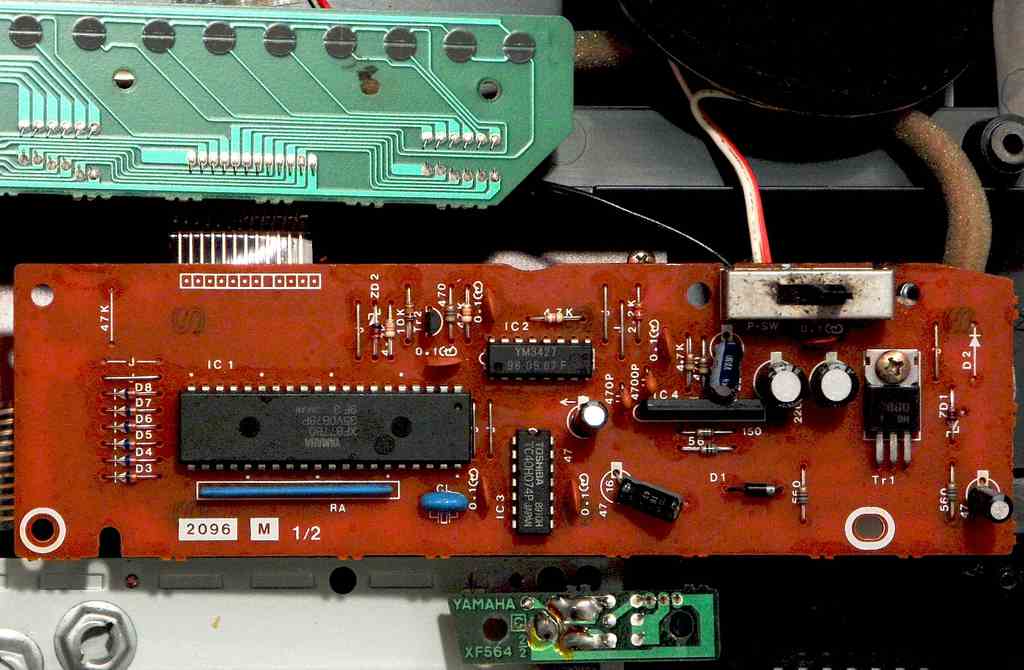
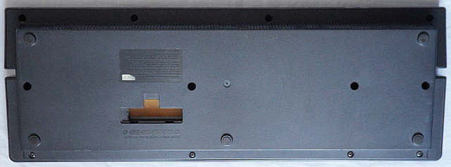
circuit bending detailsThe Yamaha PSS-80 is based on the CPU "Yamaha XF877B0" (crystal clocked @ 2.78 MHz) with squarewave sound IC "Yamaha YM3427". The power amp IC is "Toshiba TA7368P".
The CPU is apparently a "Hitachi HD6305V0" 8 bit microcontroller with internal 4 KB ROM and 192 byte RAM. Good is that the foil button panel has ordinary rubber contacts underneath
(touching carbon traces on a PCB), which makes it safe to dismantle and
modify without risk of tearing delicate contact foils.
Aaron Howald had e-mailed me the following info: "I got a damaged Yamaha PSS-80 as my 3rd bend attempt nearly 2 years ago. I found that the key press beep CAN be disabled! It comes from the CPU, at pin 5 (I just cut the line) also try playing with switching the 4 data lines in/out between the CPU and sound generator - you can get weird beats, alternate keys sounding different, etc..."disable button click The button press blip sound comes through an 4.7k resistor (next to the sound IC) from an own sound channel at CPU pin 5. You may disconnect this nuisance if you don't like it. shitshot The PSS-80 is very software controlled and makes lots of crazy stuff (as strange and variable as Casio SK-1 or TI Speak&Spell) by shorting clock pins with a resistor (e.g. 1k) or even touching them with fingers. This can make it play by itself bizarre random endless synth compositions (those don't repeat at least for 20 minutes) resembling weird C64 music. analogue tempo control? The sound IC pin 7 outputs serial data to CPU pin 33. Despite the bit pattern is more complex (binary counter?), likely only one bit is polled as a timer, because pulling this line lo (tested through 1k resistor) pauses rhythm and demo. Removing the pulldown wire continues rhythm where it was; wiggling it even steps through them faster, so it is likely the timer interrupt signal for tempo control. Thus it is likely possible (not tested by me) to feed CPU pin 33 with an external squarewave oscillator (e.g. an IC NE555) with potentiometer to build a stepless analogue tempo control with wider speed range. The sound IC pin 7 likely has to be disconnected. (In Yamaha PSS-100 this pin is not used anyway, so it is not necessary for making sound.) keyboard matrixThe keyboard matrix is grouped by 6. Except 4 lower note keys I found no eastereggs. The unused places at pin 16 do nothing, but connecting both through diodes disables the panel buttons (likely to prevent mess by omitted diodes).The CPU pin 17 is wired as key matrix out on the PCB, but in my PSS-80
it does nothing (stays lo at high resistance), so at least mine has no
drumpads easteregg (matrix entries added from PSS-125 panel schematics).
I tried pulling hi to enable pin 17 without success. Also putting diodes
in the 2 empty matrix places doesn't help. The CPU of PSS-80 and PSS-125
in service manuals have different part numbers and thus likely changed
software. But my PSS-80 also fails to enter the mentioned "test program"
(service mode), so there may be PSS-80 with different CPU revisions, of
those possibly others do support drumpads. (With Casio SA-series
there is also a matrix compatible CPU version with and without drumpads.)
The "accomp." switch is outside the matrix; it enables single finger accompaniment
while CPU pin 19 is pulled lo.
The input lines are active-low, i.e. react on GND. Any functions can
be triggered by a non- locking switch in series to a diode from one "in"
to one "out" pin.
pinout YM3427 (GE12)The Yamaha YM3427 (16 pin DIL, schematics name also "XF357A00") is the "GE12" sound IC of Yamaha PSS-80, PSS-100 and PSS-125. It was the last squarewave sound IC made by Yamaha. Apparently it can share its 6 polyphony channels among percussion and melody voices. The blip percussion has sounds made from squarewave and hissy or semi-metallic waveforms. Both are output multiplexed through a time slice DAC (6 internal channels) on a single pin. The waveforms not even return to a center voltage, but are only pulled into one direction (up from GND, to save battery?). Unlike older Yamaha keyboards, the volume envelopes of the internal generator are logarithmic; the nonlinear envelope DAC has 31 steps (5 bit) of varying height (upper end is higher). The official melody waveforms are 5 pulse widths and 3 multipulses (i.e. 2, 3 or 4 repeats of the shortest pulse followed by a pause) as "brightness" settings, but apparently the IC can produce intermediate timbres between percussion and main voice (seen by shitshot) and modulate everything in realtime under full software control of the host CPU. Pitch is transmitted as note and octave numbers (internally translated into frequency) and 2 bit detune. The ADSR envelope generator can e.g. replace release with reverb and do mandolin ring by itself, but each section seems to be controlled by only 1 bit (present od absent). There is also an internal LFO for vibrato (4 depths, 8 speeds) and tremolo and a 3 bit volume control. The waveform ("brightness") seems to be also a modulation target for envelope (e.g. 'trumpet' attack phase) and LFO (PSS-100 'honky-tonk piano'), so perhaps the concept was even to approximate a VCF. The 3 pin data bus has a 7 bit(?) serial protocol and likely includes an IRQ timer for tempo control.Thanks Skidlz (Zack Nelson) for analyzing the protocol and registers
of this undocumented sound IC. This pinout was initially measured and concluded
by me, because I only had very grainy incomplete service manual photo fragments
of Yamaha PSS-80 and PSS-100, but I later found the complete PSS-100 service
manual PDF and so could correct it.
The center 8 pins of YM3427 ("NC") are fake and completely unbondet (verified with diode mode of multitester), i.e. this sound IC is genuinely only 8 pin! The rest is camouflage to confuse the Russians (or Chinese?) - or did Yamaha consider a too small package embarrassing?? (It is really strange that on PCB pin 3 is wired to 7, 4 to GND, 13 to 9 and 14 to 10 despite they have no technical function and certainly also were not routed this way for shielding to tweak its at that time top edge highend timbre quality. ;-) ) In PSS-80 pulling pin 7 lo (tested through 1k resistor) pauses rhythm and demo (with accompaniment switching mainvoice monophonic?) while standard envelopes keep working normal, which makes me conclude that pin 7 is a timer interrupt output for tempo control. Removing the pulldown wire continues rhythm where it was; wiggling it steps through them faster. The mandolin ring is independent from this timer and internally retriggered by the envelope circuit. The pin 7 bit pattern speed on oscilloscope does not seem to change with tempo setting, but the bits between the start bit seem to vary - this may be a binary counter counting down with adjustable rate to trigger an event (IRQ?) when it reaches zero; then the counter restarts. In PSS-100 the pin 7 is not used (lo), but with pullup resistor it shows data, which hints that it is always enabled and does not need special initialization. Pin 10 looked like digital supply voltage, but is wired to what appears to be the CPU reset pin, which in normal operation stays hi at fairly high current and even slightly higher voltage (+5.3V) than pin 16. So I am not sure if pin 16 is the genuine supply voltage input, or if a crashed YM3427 can draw excessive current and so reset the CPU to prevent damage. (During shitshot I saw no such conditions.) Skidlz identified pin 10 as reset. Also in PSS-100 it is wired to the reset pin of its CPU. Data clock rate is 86875 kHz (clock of pin 1 divided by 16). Many shitshot states (strange garbled demo or accompaniments) by touching crystal pins seem to be caused by making sound IC bits run out of sync with the CPU and so interpreting them wrongly. Thus after several shitshots it tends to coincidentally re-align itself and so melody or note pitches get audible again (often with very messed up timbres). A close relative of YM3427 seems to be the sound hardware of Yamaha
PSS-20 (CPU "YM7108"),
which main voice is only monophonic but has the same waveforms.
pinout XF877B0, XG724B0The "Yamaha XF877B0" (40 pin DIL) is the CPU of Yamaha PSS-80. It controls the sound IC YM3427 and has on own sound output for button click (waveform is 3 periods of plain squarewave). It is very software controlled (visible by shitshot) and genuinely an 8 bit microcontroller "Hitachi HD6305V0" with internal 4KB ROM, 192 byte RAM and HD6800-like software features.The CPU of Yamaha PSS-125 supports additional drumpad buttons (absent in XF877B0), and while in schematics both are mentioned as "XF877B00", the "electrical parts" section in service manuals list the PSS-80 CPU as part number "XF877B00" and that of PSS-125 as "XG724B00"; in "Description" column both are refered "HD6305V0***P", which makes me conclude that the part number is the software number, while HD6305V0 refers to the generic CPU type. (The rightmost "0" seems to be not printed on components but only fill the column.) This pinout was examined by me. I only have very grainy incomplete photo
fragments of Yamaha PSS-80 service manuals. I first thought it was Motorola
HC05 (pinout from HC05 Programming Reference Guide by Freescale
Semiconductors Inc.), so I wrote a column for pin comparison, but the
Hitachi HD6305V0 datasheet matches the blurred photo perfectly.
The keyboard matrix inputs and outputs of Port B {12..16} need external pullup resistors (resistor array "13X473J"). In my PSS-80 pin 17 is not connected (wire bridge and 47k pullup resistor omitted) and does nothing due to different software number. The lo pulse of pin 16 is a bit longer than others (due to disabled pin 17??). The accomp switch input pin 19 is not in the matrix; it enables accompaniment while pulled lo, but does not respond on keyboard matrix outs, thus it is likely polled only in-between or debounced to ignore too short pulses. The unused CPU pins when desoldered are mostly lo at high resistance (I tried pulling hi to enable pin 17 without success. Also putting diodes in 2 empty matrix places doesn't help.) Pulling pin 2 lo (tested through resistor) resets the CPU at falling edge. Pulling pin 35 lo (?, even touch by fingers) locks up the CPU (no key response, partly strange static noise loops). The NUM pin 3 is a test pin (must be grounded according to HD6305V0 datasheet). It outputs a serial bit loop (frequency about 3.4 us) when pulled hi trough a 1K resistor. Reset during pullup puts it into a strange (test?) mode where most port pins (even the unused ones) are hi outs and pins 12 and 14 output serial data. Pressing certain keys changes the pin 3 bit patterns and partly makes strange high beeps or locks it up. It may be that like with Intel MCS-48 the ROM can be dumped this way. (I found a similar mode in the single chip CPU CIL-51 of Penrod AJ-430.) But because there might be a risk (if PROM) of erasing or overwriting ROM contents, I resoldered this pin back to GND. The pinout initially suggested a variant of Motorola HC05 series 8 bit MCUs (one of MC68HC05C4/C8, MC68HCL05C4/C8, MC68HC705C8, MC68HC805C4, MC68HC05C9). The HC705 is PROM and the HC805 EEPROM based. Variants "C4" have 4 KB, "C8" 8 KB and "C9" 16 KB ROM. SRAM is 176 bytes (HC705C8 supports also 304 bytes and HC05C9 352 bytes). With most Motorola variants the Port D (pin 29..36) seems to be input-only (marked "fixed input register"), which would not match the sound IC wiring. Apparently only MC68HC05C9 can use it for output, which makes it the most plausible type. This IC would contain 15936 or 15760 bytes ROM and 176 or 352 bytes SRAM. Otherwise it is the only variant with clock monitor watchdog function, which would (if enabled) make shitshot impossible. Port D seems to be useable as serial "SCI" port, which would match the serial sound IC communication. But in block diagrams arrows at pins 30..33 are marked always bi-directional, which may mean that these 4 pins can output also in other variants, so the "fixed input" note may refer only to using Port D for non-serial purpose. Pin 3 in variants with PROM or EEPROM is the programming voltage input Vpp; the XF877B0 had here its only apparent 4 letter pin name, which I considered "TEST", but I think it is "NUM" of Hitachi HD6305V0. |
A PSS-80 with 4 additional drumpad buttons {snare, cymbal, base, clave}
came out as Yamaha PSS-125. An even greater and more advanced variant
was the Yamaha PSS-100 (same case,
each 16 sounds & rhythms, better sequencer, no OBS buttons). A somewhat
similar but simpler Yamaha squarewave instrument like PSS-80 (no synth,
no accompaniment) is the small Yamaha PSS-30.
| removal of these screws voids warranty... | ||
 |
||
|
|